9 Axis Gyroscope Accelerometer Magnetic Field Diy Kit Electronic
9 Axis Gyroscope Accelerometer Magnetic Field Diy Kit Electronic
SKU:010039- guaranteeQuality checked
- Special gift cardsSpecial gift cards
- Free return Within 60 days
- Consultancy86-0755-85201155
The MPU-9150 is the world's first 9-axis MotionTracking device designed for the low power, low cost, and high performance requirements of consumer electronics equipment including smartphones, tablets and wearable sensors. And guess what? You get to play with it.
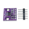
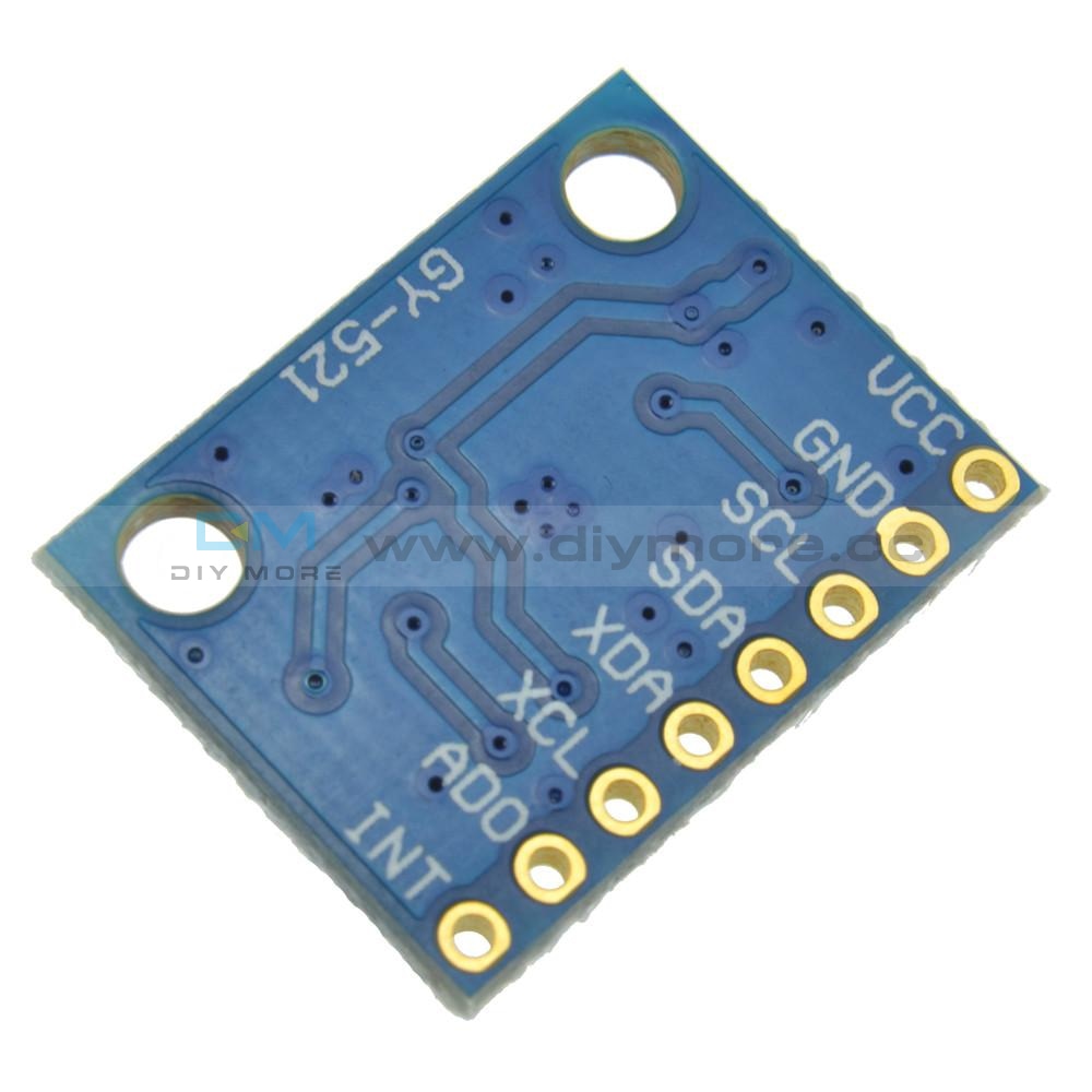
This breakout board makes it easy to prototype with the InvenSense MPU-9150 by breaking out all the pins you need to standard 0.1" spaced headers. The board also provides I2C pullup resistors and a solder jumper to switch the I2C address of the device.
The MPU-9150 is a System in Package (SiP) that combines two chips: the MPU-6050, which contains a 3-axis gyroscope, 3-axis accelerometer, and an onboard Digital Motion Processor (DMP) capable of processing complex 9-axis MotionFusion algorithms; and the AK8975, a 3-axis digital compass. The part's integrated 9-axis MotionFusion algorithms access all internal sensors to gather a full set of sensor data. The part is offered in a 4x4x1mm LGA package and is upgrade-compatible with the MPU-6050 integrated 6-axis MotionTracking device, providing a simple upgrade path and making it easy to fit on space constrained boards.
Features:
- Digital-output 9-axis MotionFusion data in rotation matrix, quaternion, Euler Angle, or raw data format
- Tri-Axis angular rate sensor (gyro) with a sensitivity up to 131 LSBs/dps and a full-scale range of ±250, ±500, ±1000, and ±2000dps
- Tri-Axis accelerometer with a programmable full scale range of ±2g, ±4g, ±8g and ±16g
- Tri-axis compass with a full scale range of ±1200µT
- Reduced settling effects and sensor drift by elimination of board-level cross-axis alignment errors between accelerometer, gyroscope, and compass
- VDD Supply voltage range of 2.4V-3.46V; VLOGIC of 1.8V±5% or VDD
- Gyro operating current: 3.6mA (full power, gyro at all rates)
- Gyro + Accel operating current: 3.8mA (full power, gyro at all rates, accel at 1kHz sample rate)
- Gyro + Accel + Compass + DMP operating current: 4.25mA (full power, gyro at all rates, accel at 1kHz sample rate, compass at 8Hz rate)
- Accel low power mode operating current: 10uA at 1Hz, 20uA at 5Hz, 70uA at 20Hz, 140uA at 40Hz
- Full Chip Idle Mode Supply Current: 8µA
- 400kHz Fast Mode I⊃2;C serial host interface
- On-chip timing generator with ±1% frequency variation over full temperature range
- 10,000g shock tolerant
- I2C Pullup Resistors populated on board.
- All Pins Broken Out to Standard 0.1" Spaced Headers
- Solder Jumper for Switching LSB of I2C Address
Purchasing & Delivery
Before you make your purchase, it’s helpful to know the measurements of the area you plan to place the furniture. You should also measure any doorways and hallways through which the furniture will pass to get to its final destination.Picking up at the store
Shopify Shop requires that all products are properly inspected BEFORE you take it home to insure there are no surprises. Our team is happy to open all packages and will assist in the inspection process. We will then reseal packages for safe transport. We encourage all customers to bring furniture pads or blankets to protect the items during transport as well as rope or tie downs. Shopify Shop will not be responsible for damage that occurs after leaving the store or during transit. It is the purchaser’s responsibility to make sure the correct items are picked up and in good condition.Delivery
Customers are able to pick the next available delivery day that best fits their schedule. However, to route stops as efficiently as possible, Shopify Shop will provide the time frame. Customers will not be able to choose a time. You will be notified in advance of your scheduled time frame. Please make sure that a responsible adult (18 years or older) will be home at that time.In preparation for your delivery, please remove existing furniture, pictures, mirrors, accessories, etc. to prevent damages. Also insure that the area where you would like your furniture placed is clear of any old furniture and any other items that may obstruct the passageway of the delivery team. Shopify Shop will deliver, assemble, and set-up your new furniture purchase and remove all packing materials from your home. Our delivery crews are not permitted to move your existing furniture or other household items. Delivery personnel will attempt to deliver the purchased items in a safe and controlled manner but will not attempt to place furniture if they feel it will result in damage to the product or your home. Delivery personnel are unable to remove doors, hoist furniture or carry furniture up more than 3 flights of stairs. An elevator must be available for deliveries to the 4th floor and above.
Other Customers also buy:
-
Translation missing: en.products.product.regular_price $4.99 USD{"id":2513525440570,"title":"9 Axis Gyroscope Accelerometer Magnetic Field Diy Kit Electronic","handle":"mpu-9150-mpu9150-9dof-9-axis-gyroscope-accelerometer-magnetic-field-diy-kit-electronic-replace-mpu6050","description":"\u003cp align=\"left\"\u003e \u003c\/p\u003e\n\u003cp\u003e\u003cspan style=\"font-size: 18.0px;\"\u003e\u003cspan style=\"font-family: arial , helvetica , sans-serif;\"\u003eThe MPU-9150 is the world's first 9-axis MotionTracking device designed for the low power, low cost, and high performance requirements of consumer electronics equipment including smartphones, tablets and wearable sensors. And guess what? You get to play with it.\u003c\/span\u003e\u003c\/span\u003e\u003c\/p\u003e\n\u003cp\u003e\u003cbr\u003e\u003cspan style=\"font-size: 18.0px;\"\u003e\u003cspan style=\"font-family: arial , helvetica , sans-serif;\"\u003eThis breakout board makes it easy to prototype with the InvenSense MPU-9150 by breaking out all the pins you need to standard 0.1\" spaced headers. The board also provides I2C pullup resistors and a solder jumper to switch the I2C address of the device.\u003c\/span\u003e\u003c\/span\u003e\u003c\/p\u003e\n\u003cp\u003e\u003cspan style=\"font-size: 18.0px;\"\u003e\u003cspan style=\"font-family: arial , helvetica , sans-serif;\"\u003e\u003c\/span\u003e\u003c\/span\u003e \u003c\/p\u003e\n\u003cp\u003e\u003cspan style=\"font-size: 18.0px;\"\u003e\u003cspan style=\"font-family: arial , helvetica , sans-serif;\"\u003eThe MPU-9150 is a System in Package (SiP) that combines two chips: the MPU-6050, which contains a 3-axis gyroscope, 3-axis accelerometer, and an onboard Digital Motion Processor (DMP) capable of processing complex 9-axis MotionFusion algorithms; and the AK8975, a 3-axis digital compass. The part's integrated 9-axis MotionFusion algorithms access all internal sensors to gather a full set of sensor data. The part is offered in a 4x4x1mm LGA package and is upgrade-compatible with the MPU-6050 integrated 6-axis MotionTracking device, providing a simple upgrade path and making it easy to fit on space constrained boards.\u003c\/span\u003e\u003c\/span\u003e\u003c\/p\u003e\n\u003cp\u003e\u003cspan style=\"font-size: 18.0px;\"\u003e\u003cspan style=\"font-family: arial , helvetica , sans-serif;\"\u003e\u003c\/span\u003e\u003c\/span\u003e \u003c\/p\u003e\n\u003cp\u003e\u003cspan style=\"font-size: 18.0px;\"\u003e\u003cspan style=\"font-family: arial , helvetica , sans-serif;\"\u003eFeatures:\u003c\/span\u003e\u003c\/span\u003e\u003c\/p\u003e\n\u003cul\u003e\n\u003cli\u003e\u003cspan style=\"font-size: 18.0px;\"\u003e\u003cspan style=\"font-family: arial , helvetica , sans-serif;\"\u003eDigital-output 9-axis MotionFusion data in rotation matrix, quaternion, Euler Angle, or raw data format\u003c\/span\u003e\u003c\/span\u003e\u003c\/li\u003e\n\u003cli\u003e\u003cspan style=\"font-size: 18.0px;\"\u003e\u003cspan style=\"font-family: arial , helvetica , sans-serif;\"\u003eTri-Axis angular rate sensor (gyro) with a sensitivity up to 131 LSBs\/dps and a full-scale range of ±250, ±500, ±1000, and ±2000dps\u003c\/span\u003e\u003c\/span\u003e\u003c\/li\u003e\n\u003cli\u003e\u003cspan style=\"font-size: 18.0px;\"\u003e\u003cspan style=\"font-family: arial , helvetica , sans-serif;\"\u003eTri-Axis accelerometer with a programmable full scale range of ±2g, ±4g, ±8g and ±16g\u003c\/span\u003e\u003c\/span\u003e\u003c\/li\u003e\n\u003cli\u003e\u003cspan style=\"font-size: 18.0px;\"\u003e\u003cspan style=\"font-family: arial , helvetica , sans-serif;\"\u003eTri-axis compass with a full scale range of ±1200µT\u003c\/span\u003e\u003c\/span\u003e\u003c\/li\u003e\n\u003cli\u003e\u003cspan style=\"font-size: 18.0px;\"\u003e\u003cspan style=\"font-family: arial , helvetica , sans-serif;\"\u003eReduced settling effects and sensor drift by elimination of board-level cross-axis alignment errors between accelerometer, gyroscope, and compass\u003c\/span\u003e\u003c\/span\u003e\u003c\/li\u003e\n\u003cli\u003e\u003cspan style=\"font-size: 18.0px;\"\u003e\u003cspan style=\"font-family: arial , helvetica , sans-serif;\"\u003eVDD Supply voltage range of 2.4V-3.46V; VLOGIC of 1.8V±5% or VDD\u003c\/span\u003e\u003c\/span\u003e\u003c\/li\u003e\n\u003cli\u003e\u003cspan style=\"font-size: 18.0px;\"\u003e\u003cspan style=\"font-family: arial , helvetica , sans-serif;\"\u003eGyro operating current: 3.6mA (full power, gyro at all rates)\u003c\/span\u003e\u003c\/span\u003e\u003c\/li\u003e\n\u003cli\u003e\u003cspan style=\"font-size: 18.0px;\"\u003e\u003cspan style=\"font-family: arial , helvetica , sans-serif;\"\u003eGyro + Accel operating current: 3.8mA (full power, gyro at all rates, accel at 1kHz sample rate)\u003c\/span\u003e\u003c\/span\u003e\u003c\/li\u003e\n\u003cli\u003e\u003cspan style=\"font-size: 18.0px;\"\u003e\u003cspan style=\"font-family: arial , helvetica , sans-serif;\"\u003eGyro + Accel + Compass + DMP operating current: 4.25mA (full power, gyro at all rates, accel at 1kHz sample rate, compass at 8Hz rate)\u003c\/span\u003e\u003c\/span\u003e\u003c\/li\u003e\n\u003cli\u003e\u003cspan style=\"font-size: 18.0px;\"\u003e\u003cspan style=\"font-family: arial , helvetica , sans-serif;\"\u003eAccel low power mode operating current: 10uA at 1Hz, 20uA at 5Hz, 70uA at 20Hz, 140uA at 40Hz\u003c\/span\u003e\u003c\/span\u003e\u003c\/li\u003e\n\u003cli\u003e\u003cspan style=\"font-size: 18.0px;\"\u003e\u003cspan style=\"font-family: arial , helvetica , sans-serif;\"\u003eFull Chip Idle Mode Supply Current: 8µA\u003c\/span\u003e\u003c\/span\u003e\u003c\/li\u003e\n\u003cli\u003e\u003cspan style=\"font-size: 18.0px;\"\u003e\u003cspan style=\"font-family: arial , helvetica , sans-serif;\"\u003e400kHz Fast Mode I⊃2;C serial host interface\u003c\/span\u003e\u003c\/span\u003e\u003c\/li\u003e\n\u003cli\u003e\u003cspan style=\"font-size: 18.0px;\"\u003e\u003cspan style=\"font-family: arial , helvetica , sans-serif;\"\u003eOn-chip timing generator with ±1% frequency variation over full temperature range\u003c\/span\u003e\u003c\/span\u003e\u003c\/li\u003e\n\u003cli\u003e\u003cspan style=\"font-size: 18.0px;\"\u003e\u003cspan style=\"font-family: arial , helvetica , sans-serif;\"\u003e10,000g shock tolerant\u003c\/span\u003e\u003c\/span\u003e\u003c\/li\u003e\n\u003cli\u003e\u003cspan style=\"font-size: 18.0px;\"\u003e\u003cspan style=\"font-family: arial , helvetica , sans-serif;\"\u003eI2C Pullup Resistors populated on board.\u003c\/span\u003e\u003c\/span\u003e\u003c\/li\u003e\n\u003cli\u003e\u003cspan style=\"font-size: 18.0px;\"\u003e\u003cspan style=\"font-family: arial , helvetica , sans-serif;\"\u003eAll Pins Broken Out to Standard 0.1\" Spaced Headers\u003c\/span\u003e\u003c\/span\u003e\u003c\/li\u003e\n\u003cli\u003e\u003cspan style=\"font-size: 18.0px;\"\u003e\u003cspan style=\"font-family: arial , helvetica , sans-serif;\"\u003eSolder Jumper for Switching LSB of I2C Address\u003c\/span\u003e\u003c\/span\u003e\u003c\/li\u003e\n\u003c\/ul\u003e","published_at":"2022-09-19T12:19:19+08:00","created_at":"2019-09-11T14:57:29+08:00","vendor":"diymore","type":"Motion Sensor Module","tags":["Featured Products","Kits"],"price":1454,"price_min":1454,"price_max":1454,"available":true,"price_varies":false,"compare_at_price":null,"compare_at_price_min":0,"compare_at_price_max":0,"compare_at_price_varies":false,"variants":[{"id":23704869994554,"title":"Default Title","option1":"Default Title","option2":null,"option3":null,"sku":"010039","requires_shipping":true,"taxable":false,"featured_image":null,"available":true,"name":"9 Axis Gyroscope Accelerometer Magnetic Field Diy Kit Electronic","public_title":null,"options":["Default Title"],"price":1454,"weight":0,"compare_at_price":null,"inventory_management":null,"barcode":"","requires_selling_plan":false,"selling_plan_allocations":[]}],"images":["\/\/www.diymore.cc\/cdn\/shop\/products\/DSC_0231_758.jpg?v=1588661155","\/\/www.diymore.cc\/cdn\/shop\/products\/DSC_0232_704.jpg?v=1588661155","\/\/www.diymore.cc\/cdn\/shop\/products\/DSC_0233_106.jpg?v=1588661155","\/\/www.diymore.cc\/cdn\/shop\/products\/DSC_0234_881.jpg?v=1588661155","\/\/www.diymore.cc\/cdn\/shop\/products\/DSC_0235_750.jpg?v=1588661155"],"featured_image":"\/\/www.diymore.cc\/cdn\/shop\/products\/DSC_0231_758.jpg?v=1588661155","options":["Title"],"media":[{"alt":"9 Axis Gyroscope Accelerometer Magnetic Field Diy Kit Electronic Motion Sensor Module","id":6679067820103,"position":1,"preview_image":{"aspect_ratio":1.0,"height":1000,"width":1000,"src":"\/\/www.diymore.cc\/cdn\/shop\/products\/DSC_0231_758.jpg?v=1588661155"},"aspect_ratio":1.0,"height":1000,"media_type":"image","src":"\/\/www.diymore.cc\/cdn\/shop\/products\/DSC_0231_758.jpg?v=1588661155","width":1000},{"alt":"9 Axis Gyroscope Accelerometer Magnetic Field Diy Kit Electronic Motion Sensor Module","id":6679068180551,"position":2,"preview_image":{"aspect_ratio":1.0,"height":1000,"width":1000,"src":"\/\/www.diymore.cc\/cdn\/shop\/products\/DSC_0232_704.jpg?v=1588661155"},"aspect_ratio":1.0,"height":1000,"media_type":"image","src":"\/\/www.diymore.cc\/cdn\/shop\/products\/DSC_0232_704.jpg?v=1588661155","width":1000},{"alt":"9 Axis Gyroscope Accelerometer Magnetic Field Diy Kit Electronic Motion Sensor Module","id":6679068311623,"position":3,"preview_image":{"aspect_ratio":1.0,"height":1000,"width":1000,"src":"\/\/www.diymore.cc\/cdn\/shop\/products\/DSC_0233_106.jpg?v=1588661155"},"aspect_ratio":1.0,"height":1000,"media_type":"image","src":"\/\/www.diymore.cc\/cdn\/shop\/products\/DSC_0233_106.jpg?v=1588661155","width":1000},{"alt":"9 Axis Gyroscope Accelerometer Magnetic Field Diy Kit Electronic Motion Sensor Module","id":6679068475463,"position":4,"preview_image":{"aspect_ratio":1.0,"height":1000,"width":1000,"src":"\/\/www.diymore.cc\/cdn\/shop\/products\/DSC_0234_881.jpg?v=1588661155"},"aspect_ratio":1.0,"height":1000,"media_type":"image","src":"\/\/www.diymore.cc\/cdn\/shop\/products\/DSC_0234_881.jpg?v=1588661155","width":1000},{"alt":"9 Axis Gyroscope Accelerometer Magnetic Field Diy Kit Electronic Motion Sensor Module","id":6679068573767,"position":5,"preview_image":{"aspect_ratio":1.0,"height":1000,"width":1000,"src":"\/\/www.diymore.cc\/cdn\/shop\/products\/DSC_0235_750.jpg?v=1588661155"},"aspect_ratio":1.0,"height":1000,"media_type":"image","src":"\/\/www.diymore.cc\/cdn\/shop\/products\/DSC_0235_750.jpg?v=1588661155","width":1000}],"requires_selling_plan":false,"selling_plan_groups":[],"content":"\u003cp align=\"left\"\u003e \u003c\/p\u003e\n\u003cp\u003e\u003cspan style=\"font-size: 18.0px;\"\u003e\u003cspan style=\"font-family: arial , helvetica , sans-serif;\"\u003eThe MPU-9150 is the world's first 9-axis MotionTracking device designed for the low power, low cost, and high performance requirements of consumer electronics equipment including smartphones, tablets and wearable sensors. And guess what? You get to play with it.\u003c\/span\u003e\u003c\/span\u003e\u003c\/p\u003e\n\u003cp\u003e\u003cbr\u003e\u003cspan style=\"font-size: 18.0px;\"\u003e\u003cspan style=\"font-family: arial , helvetica , sans-serif;\"\u003eThis breakout board makes it easy to prototype with the InvenSense MPU-9150 by breaking out all the pins you need to standard 0.1\" spaced headers. The board also provides I2C pullup resistors and a solder jumper to switch the I2C address of the device.\u003c\/span\u003e\u003c\/span\u003e\u003c\/p\u003e\n\u003cp\u003e\u003cspan style=\"font-size: 18.0px;\"\u003e\u003cspan style=\"font-family: arial , helvetica , sans-serif;\"\u003e\u003c\/span\u003e\u003c\/span\u003e \u003c\/p\u003e\n\u003cp\u003e\u003cspan style=\"font-size: 18.0px;\"\u003e\u003cspan style=\"font-family: arial , helvetica , sans-serif;\"\u003eThe MPU-9150 is a System in Package (SiP) that combines two chips: the MPU-6050, which contains a 3-axis gyroscope, 3-axis accelerometer, and an onboard Digital Motion Processor (DMP) capable of processing complex 9-axis MotionFusion algorithms; and the AK8975, a 3-axis digital compass. The part's integrated 9-axis MotionFusion algorithms access all internal sensors to gather a full set of sensor data. The part is offered in a 4x4x1mm LGA package and is upgrade-compatible with the MPU-6050 integrated 6-axis MotionTracking device, providing a simple upgrade path and making it easy to fit on space constrained boards.\u003c\/span\u003e\u003c\/span\u003e\u003c\/p\u003e\n\u003cp\u003e\u003cspan style=\"font-size: 18.0px;\"\u003e\u003cspan style=\"font-family: arial , helvetica , sans-serif;\"\u003e\u003c\/span\u003e\u003c\/span\u003e \u003c\/p\u003e\n\u003cp\u003e\u003cspan style=\"font-size: 18.0px;\"\u003e\u003cspan style=\"font-family: arial , helvetica , sans-serif;\"\u003eFeatures:\u003c\/span\u003e\u003c\/span\u003e\u003c\/p\u003e\n\u003cul\u003e\n\u003cli\u003e\u003cspan style=\"font-size: 18.0px;\"\u003e\u003cspan style=\"font-family: arial , helvetica , sans-serif;\"\u003eDigital-output 9-axis MotionFusion data in rotation matrix, quaternion, Euler Angle, or raw data format\u003c\/span\u003e\u003c\/span\u003e\u003c\/li\u003e\n\u003cli\u003e\u003cspan style=\"font-size: 18.0px;\"\u003e\u003cspan style=\"font-family: arial , helvetica , sans-serif;\"\u003eTri-Axis angular rate sensor (gyro) with a sensitivity up to 131 LSBs\/dps and a full-scale range of ±250, ±500, ±1000, and ±2000dps\u003c\/span\u003e\u003c\/span\u003e\u003c\/li\u003e\n\u003cli\u003e\u003cspan style=\"font-size: 18.0px;\"\u003e\u003cspan style=\"font-family: arial , helvetica , sans-serif;\"\u003eTri-Axis accelerometer with a programmable full scale range of ±2g, ±4g, ±8g and ±16g\u003c\/span\u003e\u003c\/span\u003e\u003c\/li\u003e\n\u003cli\u003e\u003cspan style=\"font-size: 18.0px;\"\u003e\u003cspan style=\"font-family: arial , helvetica , sans-serif;\"\u003eTri-axis compass with a full scale range of ±1200µT\u003c\/span\u003e\u003c\/span\u003e\u003c\/li\u003e\n\u003cli\u003e\u003cspan style=\"font-size: 18.0px;\"\u003e\u003cspan style=\"font-family: arial , helvetica , sans-serif;\"\u003eReduced settling effects and sensor drift by elimination of board-level cross-axis alignment errors between accelerometer, gyroscope, and compass\u003c\/span\u003e\u003c\/span\u003e\u003c\/li\u003e\n\u003cli\u003e\u003cspan style=\"font-size: 18.0px;\"\u003e\u003cspan style=\"font-family: arial , helvetica , sans-serif;\"\u003eVDD Supply voltage range of 2.4V-3.46V; VLOGIC of 1.8V±5% or VDD\u003c\/span\u003e\u003c\/span\u003e\u003c\/li\u003e\n\u003cli\u003e\u003cspan style=\"font-size: 18.0px;\"\u003e\u003cspan style=\"font-family: arial , helvetica , sans-serif;\"\u003eGyro operating current: 3.6mA (full power, gyro at all rates)\u003c\/span\u003e\u003c\/span\u003e\u003c\/li\u003e\n\u003cli\u003e\u003cspan style=\"font-size: 18.0px;\"\u003e\u003cspan style=\"font-family: arial , helvetica , sans-serif;\"\u003eGyro + Accel operating current: 3.8mA (full power, gyro at all rates, accel at 1kHz sample rate)\u003c\/span\u003e\u003c\/span\u003e\u003c\/li\u003e\n\u003cli\u003e\u003cspan style=\"font-size: 18.0px;\"\u003e\u003cspan style=\"font-family: arial , helvetica , sans-serif;\"\u003eGyro + Accel + Compass + DMP operating current: 4.25mA (full power, gyro at all rates, accel at 1kHz sample rate, compass at 8Hz rate)\u003c\/span\u003e\u003c\/span\u003e\u003c\/li\u003e\n\u003cli\u003e\u003cspan style=\"font-size: 18.0px;\"\u003e\u003cspan style=\"font-family: arial , helvetica , sans-serif;\"\u003eAccel low power mode operating current: 10uA at 1Hz, 20uA at 5Hz, 70uA at 20Hz, 140uA at 40Hz\u003c\/span\u003e\u003c\/span\u003e\u003c\/li\u003e\n\u003cli\u003e\u003cspan style=\"font-size: 18.0px;\"\u003e\u003cspan style=\"font-family: arial , helvetica , sans-serif;\"\u003eFull Chip Idle Mode Supply Current: 8µA\u003c\/span\u003e\u003c\/span\u003e\u003c\/li\u003e\n\u003cli\u003e\u003cspan style=\"font-size: 18.0px;\"\u003e\u003cspan style=\"font-family: arial , helvetica , sans-serif;\"\u003e400kHz Fast Mode I⊃2;C serial host interface\u003c\/span\u003e\u003c\/span\u003e\u003c\/li\u003e\n\u003cli\u003e\u003cspan style=\"font-size: 18.0px;\"\u003e\u003cspan style=\"font-family: arial , helvetica , sans-serif;\"\u003eOn-chip timing generator with ±1% frequency variation over full temperature range\u003c\/span\u003e\u003c\/span\u003e\u003c\/li\u003e\n\u003cli\u003e\u003cspan style=\"font-size: 18.0px;\"\u003e\u003cspan style=\"font-family: arial , helvetica , sans-serif;\"\u003e10,000g shock tolerant\u003c\/span\u003e\u003c\/span\u003e\u003c\/li\u003e\n\u003cli\u003e\u003cspan style=\"font-size: 18.0px;\"\u003e\u003cspan style=\"font-family: arial , helvetica , sans-serif;\"\u003eI2C Pullup Resistors populated on board.\u003c\/span\u003e\u003c\/span\u003e\u003c\/li\u003e\n\u003cli\u003e\u003cspan style=\"font-size: 18.0px;\"\u003e\u003cspan style=\"font-family: arial , helvetica , sans-serif;\"\u003eAll Pins Broken Out to Standard 0.1\" Spaced Headers\u003c\/span\u003e\u003c\/span\u003e\u003c\/li\u003e\n\u003cli\u003e\u003cspan style=\"font-size: 18.0px;\"\u003e\u003cspan style=\"font-family: arial , helvetica , sans-serif;\"\u003eSolder Jumper for Switching LSB of I2C Address\u003c\/span\u003e\u003c\/span\u003e\u003c\/li\u003e\n\u003c\/ul\u003e"}
-
Translation missing: en.products.product.regular_price $6.99 USD{"id":2513525440570,"title":"9 Axis Gyroscope Accelerometer Magnetic Field Diy Kit Electronic","handle":"mpu-9150-mpu9150-9dof-9-axis-gyroscope-accelerometer-magnetic-field-diy-kit-electronic-replace-mpu6050","description":"\u003cp align=\"left\"\u003e \u003c\/p\u003e\n\u003cp\u003e\u003cspan style=\"font-size: 18.0px;\"\u003e\u003cspan style=\"font-family: arial , helvetica , sans-serif;\"\u003eThe MPU-9150 is the world's first 9-axis MotionTracking device designed for the low power, low cost, and high performance requirements of consumer electronics equipment including smartphones, tablets and wearable sensors. And guess what? You get to play with it.\u003c\/span\u003e\u003c\/span\u003e\u003c\/p\u003e\n\u003cp\u003e\u003cbr\u003e\u003cspan style=\"font-size: 18.0px;\"\u003e\u003cspan style=\"font-family: arial , helvetica , sans-serif;\"\u003eThis breakout board makes it easy to prototype with the InvenSense MPU-9150 by breaking out all the pins you need to standard 0.1\" spaced headers. The board also provides I2C pullup resistors and a solder jumper to switch the I2C address of the device.\u003c\/span\u003e\u003c\/span\u003e\u003c\/p\u003e\n\u003cp\u003e\u003cspan style=\"font-size: 18.0px;\"\u003e\u003cspan style=\"font-family: arial , helvetica , sans-serif;\"\u003e\u003c\/span\u003e\u003c\/span\u003e \u003c\/p\u003e\n\u003cp\u003e\u003cspan style=\"font-size: 18.0px;\"\u003e\u003cspan style=\"font-family: arial , helvetica , sans-serif;\"\u003eThe MPU-9150 is a System in Package (SiP) that combines two chips: the MPU-6050, which contains a 3-axis gyroscope, 3-axis accelerometer, and an onboard Digital Motion Processor (DMP) capable of processing complex 9-axis MotionFusion algorithms; and the AK8975, a 3-axis digital compass. The part's integrated 9-axis MotionFusion algorithms access all internal sensors to gather a full set of sensor data. The part is offered in a 4x4x1mm LGA package and is upgrade-compatible with the MPU-6050 integrated 6-axis MotionTracking device, providing a simple upgrade path and making it easy to fit on space constrained boards.\u003c\/span\u003e\u003c\/span\u003e\u003c\/p\u003e\n\u003cp\u003e\u003cspan style=\"font-size: 18.0px;\"\u003e\u003cspan style=\"font-family: arial , helvetica , sans-serif;\"\u003e\u003c\/span\u003e\u003c\/span\u003e \u003c\/p\u003e\n\u003cp\u003e\u003cspan style=\"font-size: 18.0px;\"\u003e\u003cspan style=\"font-family: arial , helvetica , sans-serif;\"\u003eFeatures:\u003c\/span\u003e\u003c\/span\u003e\u003c\/p\u003e\n\u003cul\u003e\n\u003cli\u003e\u003cspan style=\"font-size: 18.0px;\"\u003e\u003cspan style=\"font-family: arial , helvetica , sans-serif;\"\u003eDigital-output 9-axis MotionFusion data in rotation matrix, quaternion, Euler Angle, or raw data format\u003c\/span\u003e\u003c\/span\u003e\u003c\/li\u003e\n\u003cli\u003e\u003cspan style=\"font-size: 18.0px;\"\u003e\u003cspan style=\"font-family: arial , helvetica , sans-serif;\"\u003eTri-Axis angular rate sensor (gyro) with a sensitivity up to 131 LSBs\/dps and a full-scale range of ±250, ±500, ±1000, and ±2000dps\u003c\/span\u003e\u003c\/span\u003e\u003c\/li\u003e\n\u003cli\u003e\u003cspan style=\"font-size: 18.0px;\"\u003e\u003cspan style=\"font-family: arial , helvetica , sans-serif;\"\u003eTri-Axis accelerometer with a programmable full scale range of ±2g, ±4g, ±8g and ±16g\u003c\/span\u003e\u003c\/span\u003e\u003c\/li\u003e\n\u003cli\u003e\u003cspan style=\"font-size: 18.0px;\"\u003e\u003cspan style=\"font-family: arial , helvetica , sans-serif;\"\u003eTri-axis compass with a full scale range of ±1200µT\u003c\/span\u003e\u003c\/span\u003e\u003c\/li\u003e\n\u003cli\u003e\u003cspan style=\"font-size: 18.0px;\"\u003e\u003cspan style=\"font-family: arial , helvetica , sans-serif;\"\u003eReduced settling effects and sensor drift by elimination of board-level cross-axis alignment errors between accelerometer, gyroscope, and compass\u003c\/span\u003e\u003c\/span\u003e\u003c\/li\u003e\n\u003cli\u003e\u003cspan style=\"font-size: 18.0px;\"\u003e\u003cspan style=\"font-family: arial , helvetica , sans-serif;\"\u003eVDD Supply voltage range of 2.4V-3.46V; VLOGIC of 1.8V±5% or VDD\u003c\/span\u003e\u003c\/span\u003e\u003c\/li\u003e\n\u003cli\u003e\u003cspan style=\"font-size: 18.0px;\"\u003e\u003cspan style=\"font-family: arial , helvetica , sans-serif;\"\u003eGyro operating current: 3.6mA (full power, gyro at all rates)\u003c\/span\u003e\u003c\/span\u003e\u003c\/li\u003e\n\u003cli\u003e\u003cspan style=\"font-size: 18.0px;\"\u003e\u003cspan style=\"font-family: arial , helvetica , sans-serif;\"\u003eGyro + Accel operating current: 3.8mA (full power, gyro at all rates, accel at 1kHz sample rate)\u003c\/span\u003e\u003c\/span\u003e\u003c\/li\u003e\n\u003cli\u003e\u003cspan style=\"font-size: 18.0px;\"\u003e\u003cspan style=\"font-family: arial , helvetica , sans-serif;\"\u003eGyro + Accel + Compass + DMP operating current: 4.25mA (full power, gyro at all rates, accel at 1kHz sample rate, compass at 8Hz rate)\u003c\/span\u003e\u003c\/span\u003e\u003c\/li\u003e\n\u003cli\u003e\u003cspan style=\"font-size: 18.0px;\"\u003e\u003cspan style=\"font-family: arial , helvetica , sans-serif;\"\u003eAccel low power mode operating current: 10uA at 1Hz, 20uA at 5Hz, 70uA at 20Hz, 140uA at 40Hz\u003c\/span\u003e\u003c\/span\u003e\u003c\/li\u003e\n\u003cli\u003e\u003cspan style=\"font-size: 18.0px;\"\u003e\u003cspan style=\"font-family: arial , helvetica , sans-serif;\"\u003eFull Chip Idle Mode Supply Current: 8µA\u003c\/span\u003e\u003c\/span\u003e\u003c\/li\u003e\n\u003cli\u003e\u003cspan style=\"font-size: 18.0px;\"\u003e\u003cspan style=\"font-family: arial , helvetica , sans-serif;\"\u003e400kHz Fast Mode I⊃2;C serial host interface\u003c\/span\u003e\u003c\/span\u003e\u003c\/li\u003e\n\u003cli\u003e\u003cspan style=\"font-size: 18.0px;\"\u003e\u003cspan style=\"font-family: arial , helvetica , sans-serif;\"\u003eOn-chip timing generator with ±1% frequency variation over full temperature range\u003c\/span\u003e\u003c\/span\u003e\u003c\/li\u003e\n\u003cli\u003e\u003cspan style=\"font-size: 18.0px;\"\u003e\u003cspan style=\"font-family: arial , helvetica , sans-serif;\"\u003e10,000g shock tolerant\u003c\/span\u003e\u003c\/span\u003e\u003c\/li\u003e\n\u003cli\u003e\u003cspan style=\"font-size: 18.0px;\"\u003e\u003cspan style=\"font-family: arial , helvetica , sans-serif;\"\u003eI2C Pullup Resistors populated on board.\u003c\/span\u003e\u003c\/span\u003e\u003c\/li\u003e\n\u003cli\u003e\u003cspan style=\"font-size: 18.0px;\"\u003e\u003cspan style=\"font-family: arial , helvetica , sans-serif;\"\u003eAll Pins Broken Out to Standard 0.1\" Spaced Headers\u003c\/span\u003e\u003c\/span\u003e\u003c\/li\u003e\n\u003cli\u003e\u003cspan style=\"font-size: 18.0px;\"\u003e\u003cspan style=\"font-family: arial , helvetica , sans-serif;\"\u003eSolder Jumper for Switching LSB of I2C Address\u003c\/span\u003e\u003c\/span\u003e\u003c\/li\u003e\n\u003c\/ul\u003e","published_at":"2022-09-19T12:19:19+08:00","created_at":"2019-09-11T14:57:29+08:00","vendor":"diymore","type":"Motion Sensor Module","tags":["Featured Products","Kits"],"price":1454,"price_min":1454,"price_max":1454,"available":true,"price_varies":false,"compare_at_price":null,"compare_at_price_min":0,"compare_at_price_max":0,"compare_at_price_varies":false,"variants":[{"id":23704869994554,"title":"Default Title","option1":"Default Title","option2":null,"option3":null,"sku":"010039","requires_shipping":true,"taxable":false,"featured_image":null,"available":true,"name":"9 Axis Gyroscope Accelerometer Magnetic Field Diy Kit Electronic","public_title":null,"options":["Default Title"],"price":1454,"weight":0,"compare_at_price":null,"inventory_management":null,"barcode":"","requires_selling_plan":false,"selling_plan_allocations":[]}],"images":["\/\/www.diymore.cc\/cdn\/shop\/products\/DSC_0231_758.jpg?v=1588661155","\/\/www.diymore.cc\/cdn\/shop\/products\/DSC_0232_704.jpg?v=1588661155","\/\/www.diymore.cc\/cdn\/shop\/products\/DSC_0233_106.jpg?v=1588661155","\/\/www.diymore.cc\/cdn\/shop\/products\/DSC_0234_881.jpg?v=1588661155","\/\/www.diymore.cc\/cdn\/shop\/products\/DSC_0235_750.jpg?v=1588661155"],"featured_image":"\/\/www.diymore.cc\/cdn\/shop\/products\/DSC_0231_758.jpg?v=1588661155","options":["Title"],"media":[{"alt":"9 Axis Gyroscope Accelerometer Magnetic Field Diy Kit Electronic Motion Sensor Module","id":6679067820103,"position":1,"preview_image":{"aspect_ratio":1.0,"height":1000,"width":1000,"src":"\/\/www.diymore.cc\/cdn\/shop\/products\/DSC_0231_758.jpg?v=1588661155"},"aspect_ratio":1.0,"height":1000,"media_type":"image","src":"\/\/www.diymore.cc\/cdn\/shop\/products\/DSC_0231_758.jpg?v=1588661155","width":1000},{"alt":"9 Axis Gyroscope Accelerometer Magnetic Field Diy Kit Electronic Motion Sensor Module","id":6679068180551,"position":2,"preview_image":{"aspect_ratio":1.0,"height":1000,"width":1000,"src":"\/\/www.diymore.cc\/cdn\/shop\/products\/DSC_0232_704.jpg?v=1588661155"},"aspect_ratio":1.0,"height":1000,"media_type":"image","src":"\/\/www.diymore.cc\/cdn\/shop\/products\/DSC_0232_704.jpg?v=1588661155","width":1000},{"alt":"9 Axis Gyroscope Accelerometer Magnetic Field Diy Kit Electronic Motion Sensor Module","id":6679068311623,"position":3,"preview_image":{"aspect_ratio":1.0,"height":1000,"width":1000,"src":"\/\/www.diymore.cc\/cdn\/shop\/products\/DSC_0233_106.jpg?v=1588661155"},"aspect_ratio":1.0,"height":1000,"media_type":"image","src":"\/\/www.diymore.cc\/cdn\/shop\/products\/DSC_0233_106.jpg?v=1588661155","width":1000},{"alt":"9 Axis Gyroscope Accelerometer Magnetic Field Diy Kit Electronic Motion Sensor Module","id":6679068475463,"position":4,"preview_image":{"aspect_ratio":1.0,"height":1000,"width":1000,"src":"\/\/www.diymore.cc\/cdn\/shop\/products\/DSC_0234_881.jpg?v=1588661155"},"aspect_ratio":1.0,"height":1000,"media_type":"image","src":"\/\/www.diymore.cc\/cdn\/shop\/products\/DSC_0234_881.jpg?v=1588661155","width":1000},{"alt":"9 Axis Gyroscope Accelerometer Magnetic Field Diy Kit Electronic Motion Sensor Module","id":6679068573767,"position":5,"preview_image":{"aspect_ratio":1.0,"height":1000,"width":1000,"src":"\/\/www.diymore.cc\/cdn\/shop\/products\/DSC_0235_750.jpg?v=1588661155"},"aspect_ratio":1.0,"height":1000,"media_type":"image","src":"\/\/www.diymore.cc\/cdn\/shop\/products\/DSC_0235_750.jpg?v=1588661155","width":1000}],"requires_selling_plan":false,"selling_plan_groups":[],"content":"\u003cp align=\"left\"\u003e \u003c\/p\u003e\n\u003cp\u003e\u003cspan style=\"font-size: 18.0px;\"\u003e\u003cspan style=\"font-family: arial , helvetica , sans-serif;\"\u003eThe MPU-9150 is the world's first 9-axis MotionTracking device designed for the low power, low cost, and high performance requirements of consumer electronics equipment including smartphones, tablets and wearable sensors. And guess what? You get to play with it.\u003c\/span\u003e\u003c\/span\u003e\u003c\/p\u003e\n\u003cp\u003e\u003cbr\u003e\u003cspan style=\"font-size: 18.0px;\"\u003e\u003cspan style=\"font-family: arial , helvetica , sans-serif;\"\u003eThis breakout board makes it easy to prototype with the InvenSense MPU-9150 by breaking out all the pins you need to standard 0.1\" spaced headers. The board also provides I2C pullup resistors and a solder jumper to switch the I2C address of the device.\u003c\/span\u003e\u003c\/span\u003e\u003c\/p\u003e\n\u003cp\u003e\u003cspan style=\"font-size: 18.0px;\"\u003e\u003cspan style=\"font-family: arial , helvetica , sans-serif;\"\u003e\u003c\/span\u003e\u003c\/span\u003e \u003c\/p\u003e\n\u003cp\u003e\u003cspan style=\"font-size: 18.0px;\"\u003e\u003cspan style=\"font-family: arial , helvetica , sans-serif;\"\u003eThe MPU-9150 is a System in Package (SiP) that combines two chips: the MPU-6050, which contains a 3-axis gyroscope, 3-axis accelerometer, and an onboard Digital Motion Processor (DMP) capable of processing complex 9-axis MotionFusion algorithms; and the AK8975, a 3-axis digital compass. The part's integrated 9-axis MotionFusion algorithms access all internal sensors to gather a full set of sensor data. The part is offered in a 4x4x1mm LGA package and is upgrade-compatible with the MPU-6050 integrated 6-axis MotionTracking device, providing a simple upgrade path and making it easy to fit on space constrained boards.\u003c\/span\u003e\u003c\/span\u003e\u003c\/p\u003e\n\u003cp\u003e\u003cspan style=\"font-size: 18.0px;\"\u003e\u003cspan style=\"font-family: arial , helvetica , sans-serif;\"\u003e\u003c\/span\u003e\u003c\/span\u003e \u003c\/p\u003e\n\u003cp\u003e\u003cspan style=\"font-size: 18.0px;\"\u003e\u003cspan style=\"font-family: arial , helvetica , sans-serif;\"\u003eFeatures:\u003c\/span\u003e\u003c\/span\u003e\u003c\/p\u003e\n\u003cul\u003e\n\u003cli\u003e\u003cspan style=\"font-size: 18.0px;\"\u003e\u003cspan style=\"font-family: arial , helvetica , sans-serif;\"\u003eDigital-output 9-axis MotionFusion data in rotation matrix, quaternion, Euler Angle, or raw data format\u003c\/span\u003e\u003c\/span\u003e\u003c\/li\u003e\n\u003cli\u003e\u003cspan style=\"font-size: 18.0px;\"\u003e\u003cspan style=\"font-family: arial , helvetica , sans-serif;\"\u003eTri-Axis angular rate sensor (gyro) with a sensitivity up to 131 LSBs\/dps and a full-scale range of ±250, ±500, ±1000, and ±2000dps\u003c\/span\u003e\u003c\/span\u003e\u003c\/li\u003e\n\u003cli\u003e\u003cspan style=\"font-size: 18.0px;\"\u003e\u003cspan style=\"font-family: arial , helvetica , sans-serif;\"\u003eTri-Axis accelerometer with a programmable full scale range of ±2g, ±4g, ±8g and ±16g\u003c\/span\u003e\u003c\/span\u003e\u003c\/li\u003e\n\u003cli\u003e\u003cspan style=\"font-size: 18.0px;\"\u003e\u003cspan style=\"font-family: arial , helvetica , sans-serif;\"\u003eTri-axis compass with a full scale range of ±1200µT\u003c\/span\u003e\u003c\/span\u003e\u003c\/li\u003e\n\u003cli\u003e\u003cspan style=\"font-size: 18.0px;\"\u003e\u003cspan style=\"font-family: arial , helvetica , sans-serif;\"\u003eReduced settling effects and sensor drift by elimination of board-level cross-axis alignment errors between accelerometer, gyroscope, and compass\u003c\/span\u003e\u003c\/span\u003e\u003c\/li\u003e\n\u003cli\u003e\u003cspan style=\"font-size: 18.0px;\"\u003e\u003cspan style=\"font-family: arial , helvetica , sans-serif;\"\u003eVDD Supply voltage range of 2.4V-3.46V; VLOGIC of 1.8V±5% or VDD\u003c\/span\u003e\u003c\/span\u003e\u003c\/li\u003e\n\u003cli\u003e\u003cspan style=\"font-size: 18.0px;\"\u003e\u003cspan style=\"font-family: arial , helvetica , sans-serif;\"\u003eGyro operating current: 3.6mA (full power, gyro at all rates)\u003c\/span\u003e\u003c\/span\u003e\u003c\/li\u003e\n\u003cli\u003e\u003cspan style=\"font-size: 18.0px;\"\u003e\u003cspan style=\"font-family: arial , helvetica , sans-serif;\"\u003eGyro + Accel operating current: 3.8mA (full power, gyro at all rates, accel at 1kHz sample rate)\u003c\/span\u003e\u003c\/span\u003e\u003c\/li\u003e\n\u003cli\u003e\u003cspan style=\"font-size: 18.0px;\"\u003e\u003cspan style=\"font-family: arial , helvetica , sans-serif;\"\u003eGyro + Accel + Compass + DMP operating current: 4.25mA (full power, gyro at all rates, accel at 1kHz sample rate, compass at 8Hz rate)\u003c\/span\u003e\u003c\/span\u003e\u003c\/li\u003e\n\u003cli\u003e\u003cspan style=\"font-size: 18.0px;\"\u003e\u003cspan style=\"font-family: arial , helvetica , sans-serif;\"\u003eAccel low power mode operating current: 10uA at 1Hz, 20uA at 5Hz, 70uA at 20Hz, 140uA at 40Hz\u003c\/span\u003e\u003c\/span\u003e\u003c\/li\u003e\n\u003cli\u003e\u003cspan style=\"font-size: 18.0px;\"\u003e\u003cspan style=\"font-family: arial , helvetica , sans-serif;\"\u003eFull Chip Idle Mode Supply Current: 8µA\u003c\/span\u003e\u003c\/span\u003e\u003c\/li\u003e\n\u003cli\u003e\u003cspan style=\"font-size: 18.0px;\"\u003e\u003cspan style=\"font-family: arial , helvetica , sans-serif;\"\u003e400kHz Fast Mode I⊃2;C serial host interface\u003c\/span\u003e\u003c\/span\u003e\u003c\/li\u003e\n\u003cli\u003e\u003cspan style=\"font-size: 18.0px;\"\u003e\u003cspan style=\"font-family: arial , helvetica , sans-serif;\"\u003eOn-chip timing generator with ±1% frequency variation over full temperature range\u003c\/span\u003e\u003c\/span\u003e\u003c\/li\u003e\n\u003cli\u003e\u003cspan style=\"font-size: 18.0px;\"\u003e\u003cspan style=\"font-family: arial , helvetica , sans-serif;\"\u003e10,000g shock tolerant\u003c\/span\u003e\u003c\/span\u003e\u003c\/li\u003e\n\u003cli\u003e\u003cspan style=\"font-size: 18.0px;\"\u003e\u003cspan style=\"font-family: arial , helvetica , sans-serif;\"\u003eI2C Pullup Resistors populated on board.\u003c\/span\u003e\u003c\/span\u003e\u003c\/li\u003e\n\u003cli\u003e\u003cspan style=\"font-size: 18.0px;\"\u003e\u003cspan style=\"font-family: arial , helvetica , sans-serif;\"\u003eAll Pins Broken Out to Standard 0.1\" Spaced Headers\u003c\/span\u003e\u003c\/span\u003e\u003c\/li\u003e\n\u003cli\u003e\u003cspan style=\"font-size: 18.0px;\"\u003e\u003cspan style=\"font-family: arial , helvetica , sans-serif;\"\u003eSolder Jumper for Switching LSB of I2C Address\u003c\/span\u003e\u003c\/span\u003e\u003c\/li\u003e\n\u003c\/ul\u003e"}
-
Translation missing: en.products.product.regular_price $4.99 USD{"id":2513525440570,"title":"9 Axis Gyroscope Accelerometer Magnetic Field Diy Kit Electronic","handle":"mpu-9150-mpu9150-9dof-9-axis-gyroscope-accelerometer-magnetic-field-diy-kit-electronic-replace-mpu6050","description":"\u003cp align=\"left\"\u003e \u003c\/p\u003e\n\u003cp\u003e\u003cspan style=\"font-size: 18.0px;\"\u003e\u003cspan style=\"font-family: arial , helvetica , sans-serif;\"\u003eThe MPU-9150 is the world's first 9-axis MotionTracking device designed for the low power, low cost, and high performance requirements of consumer electronics equipment including smartphones, tablets and wearable sensors. And guess what? You get to play with it.\u003c\/span\u003e\u003c\/span\u003e\u003c\/p\u003e\n\u003cp\u003e\u003cbr\u003e\u003cspan style=\"font-size: 18.0px;\"\u003e\u003cspan style=\"font-family: arial , helvetica , sans-serif;\"\u003eThis breakout board makes it easy to prototype with the InvenSense MPU-9150 by breaking out all the pins you need to standard 0.1\" spaced headers. The board also provides I2C pullup resistors and a solder jumper to switch the I2C address of the device.\u003c\/span\u003e\u003c\/span\u003e\u003c\/p\u003e\n\u003cp\u003e\u003cspan style=\"font-size: 18.0px;\"\u003e\u003cspan style=\"font-family: arial , helvetica , sans-serif;\"\u003e\u003c\/span\u003e\u003c\/span\u003e \u003c\/p\u003e\n\u003cp\u003e\u003cspan style=\"font-size: 18.0px;\"\u003e\u003cspan style=\"font-family: arial , helvetica , sans-serif;\"\u003eThe MPU-9150 is a System in Package (SiP) that combines two chips: the MPU-6050, which contains a 3-axis gyroscope, 3-axis accelerometer, and an onboard Digital Motion Processor (DMP) capable of processing complex 9-axis MotionFusion algorithms; and the AK8975, a 3-axis digital compass. The part's integrated 9-axis MotionFusion algorithms access all internal sensors to gather a full set of sensor data. The part is offered in a 4x4x1mm LGA package and is upgrade-compatible with the MPU-6050 integrated 6-axis MotionTracking device, providing a simple upgrade path and making it easy to fit on space constrained boards.\u003c\/span\u003e\u003c\/span\u003e\u003c\/p\u003e\n\u003cp\u003e\u003cspan style=\"font-size: 18.0px;\"\u003e\u003cspan style=\"font-family: arial , helvetica , sans-serif;\"\u003e\u003c\/span\u003e\u003c\/span\u003e \u003c\/p\u003e\n\u003cp\u003e\u003cspan style=\"font-size: 18.0px;\"\u003e\u003cspan style=\"font-family: arial , helvetica , sans-serif;\"\u003eFeatures:\u003c\/span\u003e\u003c\/span\u003e\u003c\/p\u003e\n\u003cul\u003e\n\u003cli\u003e\u003cspan style=\"font-size: 18.0px;\"\u003e\u003cspan style=\"font-family: arial , helvetica , sans-serif;\"\u003eDigital-output 9-axis MotionFusion data in rotation matrix, quaternion, Euler Angle, or raw data format\u003c\/span\u003e\u003c\/span\u003e\u003c\/li\u003e\n\u003cli\u003e\u003cspan style=\"font-size: 18.0px;\"\u003e\u003cspan style=\"font-family: arial , helvetica , sans-serif;\"\u003eTri-Axis angular rate sensor (gyro) with a sensitivity up to 131 LSBs\/dps and a full-scale range of ±250, ±500, ±1000, and ±2000dps\u003c\/span\u003e\u003c\/span\u003e\u003c\/li\u003e\n\u003cli\u003e\u003cspan style=\"font-size: 18.0px;\"\u003e\u003cspan style=\"font-family: arial , helvetica , sans-serif;\"\u003eTri-Axis accelerometer with a programmable full scale range of ±2g, ±4g, ±8g and ±16g\u003c\/span\u003e\u003c\/span\u003e\u003c\/li\u003e\n\u003cli\u003e\u003cspan style=\"font-size: 18.0px;\"\u003e\u003cspan style=\"font-family: arial , helvetica , sans-serif;\"\u003eTri-axis compass with a full scale range of ±1200µT\u003c\/span\u003e\u003c\/span\u003e\u003c\/li\u003e\n\u003cli\u003e\u003cspan style=\"font-size: 18.0px;\"\u003e\u003cspan style=\"font-family: arial , helvetica , sans-serif;\"\u003eReduced settling effects and sensor drift by elimination of board-level cross-axis alignment errors between accelerometer, gyroscope, and compass\u003c\/span\u003e\u003c\/span\u003e\u003c\/li\u003e\n\u003cli\u003e\u003cspan style=\"font-size: 18.0px;\"\u003e\u003cspan style=\"font-family: arial , helvetica , sans-serif;\"\u003eVDD Supply voltage range of 2.4V-3.46V; VLOGIC of 1.8V±5% or VDD\u003c\/span\u003e\u003c\/span\u003e\u003c\/li\u003e\n\u003cli\u003e\u003cspan style=\"font-size: 18.0px;\"\u003e\u003cspan style=\"font-family: arial , helvetica , sans-serif;\"\u003eGyro operating current: 3.6mA (full power, gyro at all rates)\u003c\/span\u003e\u003c\/span\u003e\u003c\/li\u003e\n\u003cli\u003e\u003cspan style=\"font-size: 18.0px;\"\u003e\u003cspan style=\"font-family: arial , helvetica , sans-serif;\"\u003eGyro + Accel operating current: 3.8mA (full power, gyro at all rates, accel at 1kHz sample rate)\u003c\/span\u003e\u003c\/span\u003e\u003c\/li\u003e\n\u003cli\u003e\u003cspan style=\"font-size: 18.0px;\"\u003e\u003cspan style=\"font-family: arial , helvetica , sans-serif;\"\u003eGyro + Accel + Compass + DMP operating current: 4.25mA (full power, gyro at all rates, accel at 1kHz sample rate, compass at 8Hz rate)\u003c\/span\u003e\u003c\/span\u003e\u003c\/li\u003e\n\u003cli\u003e\u003cspan style=\"font-size: 18.0px;\"\u003e\u003cspan style=\"font-family: arial , helvetica , sans-serif;\"\u003eAccel low power mode operating current: 10uA at 1Hz, 20uA at 5Hz, 70uA at 20Hz, 140uA at 40Hz\u003c\/span\u003e\u003c\/span\u003e\u003c\/li\u003e\n\u003cli\u003e\u003cspan style=\"font-size: 18.0px;\"\u003e\u003cspan style=\"font-family: arial , helvetica , sans-serif;\"\u003eFull Chip Idle Mode Supply Current: 8µA\u003c\/span\u003e\u003c\/span\u003e\u003c\/li\u003e\n\u003cli\u003e\u003cspan style=\"font-size: 18.0px;\"\u003e\u003cspan style=\"font-family: arial , helvetica , sans-serif;\"\u003e400kHz Fast Mode I⊃2;C serial host interface\u003c\/span\u003e\u003c\/span\u003e\u003c\/li\u003e\n\u003cli\u003e\u003cspan style=\"font-size: 18.0px;\"\u003e\u003cspan style=\"font-family: arial , helvetica , sans-serif;\"\u003eOn-chip timing generator with ±1% frequency variation over full temperature range\u003c\/span\u003e\u003c\/span\u003e\u003c\/li\u003e\n\u003cli\u003e\u003cspan style=\"font-size: 18.0px;\"\u003e\u003cspan style=\"font-family: arial , helvetica , sans-serif;\"\u003e10,000g shock tolerant\u003c\/span\u003e\u003c\/span\u003e\u003c\/li\u003e\n\u003cli\u003e\u003cspan style=\"font-size: 18.0px;\"\u003e\u003cspan style=\"font-family: arial , helvetica , sans-serif;\"\u003eI2C Pullup Resistors populated on board.\u003c\/span\u003e\u003c\/span\u003e\u003c\/li\u003e\n\u003cli\u003e\u003cspan style=\"font-size: 18.0px;\"\u003e\u003cspan style=\"font-family: arial , helvetica , sans-serif;\"\u003eAll Pins Broken Out to Standard 0.1\" Spaced Headers\u003c\/span\u003e\u003c\/span\u003e\u003c\/li\u003e\n\u003cli\u003e\u003cspan style=\"font-size: 18.0px;\"\u003e\u003cspan style=\"font-family: arial , helvetica , sans-serif;\"\u003eSolder Jumper for Switching LSB of I2C Address\u003c\/span\u003e\u003c\/span\u003e\u003c\/li\u003e\n\u003c\/ul\u003e","published_at":"2022-09-19T12:19:19+08:00","created_at":"2019-09-11T14:57:29+08:00","vendor":"diymore","type":"Motion Sensor Module","tags":["Featured Products","Kits"],"price":1454,"price_min":1454,"price_max":1454,"available":true,"price_varies":false,"compare_at_price":null,"compare_at_price_min":0,"compare_at_price_max":0,"compare_at_price_varies":false,"variants":[{"id":23704869994554,"title":"Default Title","option1":"Default Title","option2":null,"option3":null,"sku":"010039","requires_shipping":true,"taxable":false,"featured_image":null,"available":true,"name":"9 Axis Gyroscope Accelerometer Magnetic Field Diy Kit Electronic","public_title":null,"options":["Default Title"],"price":1454,"weight":0,"compare_at_price":null,"inventory_management":null,"barcode":"","requires_selling_plan":false,"selling_plan_allocations":[]}],"images":["\/\/www.diymore.cc\/cdn\/shop\/products\/DSC_0231_758.jpg?v=1588661155","\/\/www.diymore.cc\/cdn\/shop\/products\/DSC_0232_704.jpg?v=1588661155","\/\/www.diymore.cc\/cdn\/shop\/products\/DSC_0233_106.jpg?v=1588661155","\/\/www.diymore.cc\/cdn\/shop\/products\/DSC_0234_881.jpg?v=1588661155","\/\/www.diymore.cc\/cdn\/shop\/products\/DSC_0235_750.jpg?v=1588661155"],"featured_image":"\/\/www.diymore.cc\/cdn\/shop\/products\/DSC_0231_758.jpg?v=1588661155","options":["Title"],"media":[{"alt":"9 Axis Gyroscope Accelerometer Magnetic Field Diy Kit Electronic Motion Sensor Module","id":6679067820103,"position":1,"preview_image":{"aspect_ratio":1.0,"height":1000,"width":1000,"src":"\/\/www.diymore.cc\/cdn\/shop\/products\/DSC_0231_758.jpg?v=1588661155"},"aspect_ratio":1.0,"height":1000,"media_type":"image","src":"\/\/www.diymore.cc\/cdn\/shop\/products\/DSC_0231_758.jpg?v=1588661155","width":1000},{"alt":"9 Axis Gyroscope Accelerometer Magnetic Field Diy Kit Electronic Motion Sensor Module","id":6679068180551,"position":2,"preview_image":{"aspect_ratio":1.0,"height":1000,"width":1000,"src":"\/\/www.diymore.cc\/cdn\/shop\/products\/DSC_0232_704.jpg?v=1588661155"},"aspect_ratio":1.0,"height":1000,"media_type":"image","src":"\/\/www.diymore.cc\/cdn\/shop\/products\/DSC_0232_704.jpg?v=1588661155","width":1000},{"alt":"9 Axis Gyroscope Accelerometer Magnetic Field Diy Kit Electronic Motion Sensor Module","id":6679068311623,"position":3,"preview_image":{"aspect_ratio":1.0,"height":1000,"width":1000,"src":"\/\/www.diymore.cc\/cdn\/shop\/products\/DSC_0233_106.jpg?v=1588661155"},"aspect_ratio":1.0,"height":1000,"media_type":"image","src":"\/\/www.diymore.cc\/cdn\/shop\/products\/DSC_0233_106.jpg?v=1588661155","width":1000},{"alt":"9 Axis Gyroscope Accelerometer Magnetic Field Diy Kit Electronic Motion Sensor Module","id":6679068475463,"position":4,"preview_image":{"aspect_ratio":1.0,"height":1000,"width":1000,"src":"\/\/www.diymore.cc\/cdn\/shop\/products\/DSC_0234_881.jpg?v=1588661155"},"aspect_ratio":1.0,"height":1000,"media_type":"image","src":"\/\/www.diymore.cc\/cdn\/shop\/products\/DSC_0234_881.jpg?v=1588661155","width":1000},{"alt":"9 Axis Gyroscope Accelerometer Magnetic Field Diy Kit Electronic Motion Sensor Module","id":6679068573767,"position":5,"preview_image":{"aspect_ratio":1.0,"height":1000,"width":1000,"src":"\/\/www.diymore.cc\/cdn\/shop\/products\/DSC_0235_750.jpg?v=1588661155"},"aspect_ratio":1.0,"height":1000,"media_type":"image","src":"\/\/www.diymore.cc\/cdn\/shop\/products\/DSC_0235_750.jpg?v=1588661155","width":1000}],"requires_selling_plan":false,"selling_plan_groups":[],"content":"\u003cp align=\"left\"\u003e \u003c\/p\u003e\n\u003cp\u003e\u003cspan style=\"font-size: 18.0px;\"\u003e\u003cspan style=\"font-family: arial , helvetica , sans-serif;\"\u003eThe MPU-9150 is the world's first 9-axis MotionTracking device designed for the low power, low cost, and high performance requirements of consumer electronics equipment including smartphones, tablets and wearable sensors. And guess what? You get to play with it.\u003c\/span\u003e\u003c\/span\u003e\u003c\/p\u003e\n\u003cp\u003e\u003cbr\u003e\u003cspan style=\"font-size: 18.0px;\"\u003e\u003cspan style=\"font-family: arial , helvetica , sans-serif;\"\u003eThis breakout board makes it easy to prototype with the InvenSense MPU-9150 by breaking out all the pins you need to standard 0.1\" spaced headers. The board also provides I2C pullup resistors and a solder jumper to switch the I2C address of the device.\u003c\/span\u003e\u003c\/span\u003e\u003c\/p\u003e\n\u003cp\u003e\u003cspan style=\"font-size: 18.0px;\"\u003e\u003cspan style=\"font-family: arial , helvetica , sans-serif;\"\u003e\u003c\/span\u003e\u003c\/span\u003e \u003c\/p\u003e\n\u003cp\u003e\u003cspan style=\"font-size: 18.0px;\"\u003e\u003cspan style=\"font-family: arial , helvetica , sans-serif;\"\u003eThe MPU-9150 is a System in Package (SiP) that combines two chips: the MPU-6050, which contains a 3-axis gyroscope, 3-axis accelerometer, and an onboard Digital Motion Processor (DMP) capable of processing complex 9-axis MotionFusion algorithms; and the AK8975, a 3-axis digital compass. The part's integrated 9-axis MotionFusion algorithms access all internal sensors to gather a full set of sensor data. The part is offered in a 4x4x1mm LGA package and is upgrade-compatible with the MPU-6050 integrated 6-axis MotionTracking device, providing a simple upgrade path and making it easy to fit on space constrained boards.\u003c\/span\u003e\u003c\/span\u003e\u003c\/p\u003e\n\u003cp\u003e\u003cspan style=\"font-size: 18.0px;\"\u003e\u003cspan style=\"font-family: arial , helvetica , sans-serif;\"\u003e\u003c\/span\u003e\u003c\/span\u003e \u003c\/p\u003e\n\u003cp\u003e\u003cspan style=\"font-size: 18.0px;\"\u003e\u003cspan style=\"font-family: arial , helvetica , sans-serif;\"\u003eFeatures:\u003c\/span\u003e\u003c\/span\u003e\u003c\/p\u003e\n\u003cul\u003e\n\u003cli\u003e\u003cspan style=\"font-size: 18.0px;\"\u003e\u003cspan style=\"font-family: arial , helvetica , sans-serif;\"\u003eDigital-output 9-axis MotionFusion data in rotation matrix, quaternion, Euler Angle, or raw data format\u003c\/span\u003e\u003c\/span\u003e\u003c\/li\u003e\n\u003cli\u003e\u003cspan style=\"font-size: 18.0px;\"\u003e\u003cspan style=\"font-family: arial , helvetica , sans-serif;\"\u003eTri-Axis angular rate sensor (gyro) with a sensitivity up to 131 LSBs\/dps and a full-scale range of ±250, ±500, ±1000, and ±2000dps\u003c\/span\u003e\u003c\/span\u003e\u003c\/li\u003e\n\u003cli\u003e\u003cspan style=\"font-size: 18.0px;\"\u003e\u003cspan style=\"font-family: arial , helvetica , sans-serif;\"\u003eTri-Axis accelerometer with a programmable full scale range of ±2g, ±4g, ±8g and ±16g\u003c\/span\u003e\u003c\/span\u003e\u003c\/li\u003e\n\u003cli\u003e\u003cspan style=\"font-size: 18.0px;\"\u003e\u003cspan style=\"font-family: arial , helvetica , sans-serif;\"\u003eTri-axis compass with a full scale range of ±1200µT\u003c\/span\u003e\u003c\/span\u003e\u003c\/li\u003e\n\u003cli\u003e\u003cspan style=\"font-size: 18.0px;\"\u003e\u003cspan style=\"font-family: arial , helvetica , sans-serif;\"\u003eReduced settling effects and sensor drift by elimination of board-level cross-axis alignment errors between accelerometer, gyroscope, and compass\u003c\/span\u003e\u003c\/span\u003e\u003c\/li\u003e\n\u003cli\u003e\u003cspan style=\"font-size: 18.0px;\"\u003e\u003cspan style=\"font-family: arial , helvetica , sans-serif;\"\u003eVDD Supply voltage range of 2.4V-3.46V; VLOGIC of 1.8V±5% or VDD\u003c\/span\u003e\u003c\/span\u003e\u003c\/li\u003e\n\u003cli\u003e\u003cspan style=\"font-size: 18.0px;\"\u003e\u003cspan style=\"font-family: arial , helvetica , sans-serif;\"\u003eGyro operating current: 3.6mA (full power, gyro at all rates)\u003c\/span\u003e\u003c\/span\u003e\u003c\/li\u003e\n\u003cli\u003e\u003cspan style=\"font-size: 18.0px;\"\u003e\u003cspan style=\"font-family: arial , helvetica , sans-serif;\"\u003eGyro + Accel operating current: 3.8mA (full power, gyro at all rates, accel at 1kHz sample rate)\u003c\/span\u003e\u003c\/span\u003e\u003c\/li\u003e\n\u003cli\u003e\u003cspan style=\"font-size: 18.0px;\"\u003e\u003cspan style=\"font-family: arial , helvetica , sans-serif;\"\u003eGyro + Accel + Compass + DMP operating current: 4.25mA (full power, gyro at all rates, accel at 1kHz sample rate, compass at 8Hz rate)\u003c\/span\u003e\u003c\/span\u003e\u003c\/li\u003e\n\u003cli\u003e\u003cspan style=\"font-size: 18.0px;\"\u003e\u003cspan style=\"font-family: arial , helvetica , sans-serif;\"\u003eAccel low power mode operating current: 10uA at 1Hz, 20uA at 5Hz, 70uA at 20Hz, 140uA at 40Hz\u003c\/span\u003e\u003c\/span\u003e\u003c\/li\u003e\n\u003cli\u003e\u003cspan style=\"font-size: 18.0px;\"\u003e\u003cspan style=\"font-family: arial , helvetica , sans-serif;\"\u003eFull Chip Idle Mode Supply Current: 8µA\u003c\/span\u003e\u003c\/span\u003e\u003c\/li\u003e\n\u003cli\u003e\u003cspan style=\"font-size: 18.0px;\"\u003e\u003cspan style=\"font-family: arial , helvetica , sans-serif;\"\u003e400kHz Fast Mode I⊃2;C serial host interface\u003c\/span\u003e\u003c\/span\u003e\u003c\/li\u003e\n\u003cli\u003e\u003cspan style=\"font-size: 18.0px;\"\u003e\u003cspan style=\"font-family: arial , helvetica , sans-serif;\"\u003eOn-chip timing generator with ±1% frequency variation over full temperature range\u003c\/span\u003e\u003c\/span\u003e\u003c\/li\u003e\n\u003cli\u003e\u003cspan style=\"font-size: 18.0px;\"\u003e\u003cspan style=\"font-family: arial , helvetica , sans-serif;\"\u003e10,000g shock tolerant\u003c\/span\u003e\u003c\/span\u003e\u003c\/li\u003e\n\u003cli\u003e\u003cspan style=\"font-size: 18.0px;\"\u003e\u003cspan style=\"font-family: arial , helvetica , sans-serif;\"\u003eI2C Pullup Resistors populated on board.\u003c\/span\u003e\u003c\/span\u003e\u003c\/li\u003e\n\u003cli\u003e\u003cspan style=\"font-size: 18.0px;\"\u003e\u003cspan style=\"font-family: arial , helvetica , sans-serif;\"\u003eAll Pins Broken Out to Standard 0.1\" Spaced Headers\u003c\/span\u003e\u003c\/span\u003e\u003c\/li\u003e\n\u003cli\u003e\u003cspan style=\"font-size: 18.0px;\"\u003e\u003cspan style=\"font-family: arial , helvetica , sans-serif;\"\u003eSolder Jumper for Switching LSB of I2C Address\u003c\/span\u003e\u003c\/span\u003e\u003c\/li\u003e\n\u003c\/ul\u003e"}
-
Translation missing: en.products.product.regular_price $5.99 USD{"id":2513525440570,"title":"9 Axis Gyroscope Accelerometer Magnetic Field Diy Kit Electronic","handle":"mpu-9150-mpu9150-9dof-9-axis-gyroscope-accelerometer-magnetic-field-diy-kit-electronic-replace-mpu6050","description":"\u003cp align=\"left\"\u003e \u003c\/p\u003e\n\u003cp\u003e\u003cspan style=\"font-size: 18.0px;\"\u003e\u003cspan style=\"font-family: arial , helvetica , sans-serif;\"\u003eThe MPU-9150 is the world's first 9-axis MotionTracking device designed for the low power, low cost, and high performance requirements of consumer electronics equipment including smartphones, tablets and wearable sensors. And guess what? You get to play with it.\u003c\/span\u003e\u003c\/span\u003e\u003c\/p\u003e\n\u003cp\u003e\u003cbr\u003e\u003cspan style=\"font-size: 18.0px;\"\u003e\u003cspan style=\"font-family: arial , helvetica , sans-serif;\"\u003eThis breakout board makes it easy to prototype with the InvenSense MPU-9150 by breaking out all the pins you need to standard 0.1\" spaced headers. The board also provides I2C pullup resistors and a solder jumper to switch the I2C address of the device.\u003c\/span\u003e\u003c\/span\u003e\u003c\/p\u003e\n\u003cp\u003e\u003cspan style=\"font-size: 18.0px;\"\u003e\u003cspan style=\"font-family: arial , helvetica , sans-serif;\"\u003e\u003c\/span\u003e\u003c\/span\u003e \u003c\/p\u003e\n\u003cp\u003e\u003cspan style=\"font-size: 18.0px;\"\u003e\u003cspan style=\"font-family: arial , helvetica , sans-serif;\"\u003eThe MPU-9150 is a System in Package (SiP) that combines two chips: the MPU-6050, which contains a 3-axis gyroscope, 3-axis accelerometer, and an onboard Digital Motion Processor (DMP) capable of processing complex 9-axis MotionFusion algorithms; and the AK8975, a 3-axis digital compass. The part's integrated 9-axis MotionFusion algorithms access all internal sensors to gather a full set of sensor data. The part is offered in a 4x4x1mm LGA package and is upgrade-compatible with the MPU-6050 integrated 6-axis MotionTracking device, providing a simple upgrade path and making it easy to fit on space constrained boards.\u003c\/span\u003e\u003c\/span\u003e\u003c\/p\u003e\n\u003cp\u003e\u003cspan style=\"font-size: 18.0px;\"\u003e\u003cspan style=\"font-family: arial , helvetica , sans-serif;\"\u003e\u003c\/span\u003e\u003c\/span\u003e \u003c\/p\u003e\n\u003cp\u003e\u003cspan style=\"font-size: 18.0px;\"\u003e\u003cspan style=\"font-family: arial , helvetica , sans-serif;\"\u003eFeatures:\u003c\/span\u003e\u003c\/span\u003e\u003c\/p\u003e\n\u003cul\u003e\n\u003cli\u003e\u003cspan style=\"font-size: 18.0px;\"\u003e\u003cspan style=\"font-family: arial , helvetica , sans-serif;\"\u003eDigital-output 9-axis MotionFusion data in rotation matrix, quaternion, Euler Angle, or raw data format\u003c\/span\u003e\u003c\/span\u003e\u003c\/li\u003e\n\u003cli\u003e\u003cspan style=\"font-size: 18.0px;\"\u003e\u003cspan style=\"font-family: arial , helvetica , sans-serif;\"\u003eTri-Axis angular rate sensor (gyro) with a sensitivity up to 131 LSBs\/dps and a full-scale range of ±250, ±500, ±1000, and ±2000dps\u003c\/span\u003e\u003c\/span\u003e\u003c\/li\u003e\n\u003cli\u003e\u003cspan style=\"font-size: 18.0px;\"\u003e\u003cspan style=\"font-family: arial , helvetica , sans-serif;\"\u003eTri-Axis accelerometer with a programmable full scale range of ±2g, ±4g, ±8g and ±16g\u003c\/span\u003e\u003c\/span\u003e\u003c\/li\u003e\n\u003cli\u003e\u003cspan style=\"font-size: 18.0px;\"\u003e\u003cspan style=\"font-family: arial , helvetica , sans-serif;\"\u003eTri-axis compass with a full scale range of ±1200µT\u003c\/span\u003e\u003c\/span\u003e\u003c\/li\u003e\n\u003cli\u003e\u003cspan style=\"font-size: 18.0px;\"\u003e\u003cspan style=\"font-family: arial , helvetica , sans-serif;\"\u003eReduced settling effects and sensor drift by elimination of board-level cross-axis alignment errors between accelerometer, gyroscope, and compass\u003c\/span\u003e\u003c\/span\u003e\u003c\/li\u003e\n\u003cli\u003e\u003cspan style=\"font-size: 18.0px;\"\u003e\u003cspan style=\"font-family: arial , helvetica , sans-serif;\"\u003eVDD Supply voltage range of 2.4V-3.46V; VLOGIC of 1.8V±5% or VDD\u003c\/span\u003e\u003c\/span\u003e\u003c\/li\u003e\n\u003cli\u003e\u003cspan style=\"font-size: 18.0px;\"\u003e\u003cspan style=\"font-family: arial , helvetica , sans-serif;\"\u003eGyro operating current: 3.6mA (full power, gyro at all rates)\u003c\/span\u003e\u003c\/span\u003e\u003c\/li\u003e\n\u003cli\u003e\u003cspan style=\"font-size: 18.0px;\"\u003e\u003cspan style=\"font-family: arial , helvetica , sans-serif;\"\u003eGyro + Accel operating current: 3.8mA (full power, gyro at all rates, accel at 1kHz sample rate)\u003c\/span\u003e\u003c\/span\u003e\u003c\/li\u003e\n\u003cli\u003e\u003cspan style=\"font-size: 18.0px;\"\u003e\u003cspan style=\"font-family: arial , helvetica , sans-serif;\"\u003eGyro + Accel + Compass + DMP operating current: 4.25mA (full power, gyro at all rates, accel at 1kHz sample rate, compass at 8Hz rate)\u003c\/span\u003e\u003c\/span\u003e\u003c\/li\u003e\n\u003cli\u003e\u003cspan style=\"font-size: 18.0px;\"\u003e\u003cspan style=\"font-family: arial , helvetica , sans-serif;\"\u003eAccel low power mode operating current: 10uA at 1Hz, 20uA at 5Hz, 70uA at 20Hz, 140uA at 40Hz\u003c\/span\u003e\u003c\/span\u003e\u003c\/li\u003e\n\u003cli\u003e\u003cspan style=\"font-size: 18.0px;\"\u003e\u003cspan style=\"font-family: arial , helvetica , sans-serif;\"\u003eFull Chip Idle Mode Supply Current: 8µA\u003c\/span\u003e\u003c\/span\u003e\u003c\/li\u003e\n\u003cli\u003e\u003cspan style=\"font-size: 18.0px;\"\u003e\u003cspan style=\"font-family: arial , helvetica , sans-serif;\"\u003e400kHz Fast Mode I⊃2;C serial host interface\u003c\/span\u003e\u003c\/span\u003e\u003c\/li\u003e\n\u003cli\u003e\u003cspan style=\"font-size: 18.0px;\"\u003e\u003cspan style=\"font-family: arial , helvetica , sans-serif;\"\u003eOn-chip timing generator with ±1% frequency variation over full temperature range\u003c\/span\u003e\u003c\/span\u003e\u003c\/li\u003e\n\u003cli\u003e\u003cspan style=\"font-size: 18.0px;\"\u003e\u003cspan style=\"font-family: arial , helvetica , sans-serif;\"\u003e10,000g shock tolerant\u003c\/span\u003e\u003c\/span\u003e\u003c\/li\u003e\n\u003cli\u003e\u003cspan style=\"font-size: 18.0px;\"\u003e\u003cspan style=\"font-family: arial , helvetica , sans-serif;\"\u003eI2C Pullup Resistors populated on board.\u003c\/span\u003e\u003c\/span\u003e\u003c\/li\u003e\n\u003cli\u003e\u003cspan style=\"font-size: 18.0px;\"\u003e\u003cspan style=\"font-family: arial , helvetica , sans-serif;\"\u003eAll Pins Broken Out to Standard 0.1\" Spaced Headers\u003c\/span\u003e\u003c\/span\u003e\u003c\/li\u003e\n\u003cli\u003e\u003cspan style=\"font-size: 18.0px;\"\u003e\u003cspan style=\"font-family: arial , helvetica , sans-serif;\"\u003eSolder Jumper for Switching LSB of I2C Address\u003c\/span\u003e\u003c\/span\u003e\u003c\/li\u003e\n\u003c\/ul\u003e","published_at":"2022-09-19T12:19:19+08:00","created_at":"2019-09-11T14:57:29+08:00","vendor":"diymore","type":"Motion Sensor Module","tags":["Featured Products","Kits"],"price":1454,"price_min":1454,"price_max":1454,"available":true,"price_varies":false,"compare_at_price":null,"compare_at_price_min":0,"compare_at_price_max":0,"compare_at_price_varies":false,"variants":[{"id":23704869994554,"title":"Default Title","option1":"Default Title","option2":null,"option3":null,"sku":"010039","requires_shipping":true,"taxable":false,"featured_image":null,"available":true,"name":"9 Axis Gyroscope Accelerometer Magnetic Field Diy Kit Electronic","public_title":null,"options":["Default Title"],"price":1454,"weight":0,"compare_at_price":null,"inventory_management":null,"barcode":"","requires_selling_plan":false,"selling_plan_allocations":[]}],"images":["\/\/www.diymore.cc\/cdn\/shop\/products\/DSC_0231_758.jpg?v=1588661155","\/\/www.diymore.cc\/cdn\/shop\/products\/DSC_0232_704.jpg?v=1588661155","\/\/www.diymore.cc\/cdn\/shop\/products\/DSC_0233_106.jpg?v=1588661155","\/\/www.diymore.cc\/cdn\/shop\/products\/DSC_0234_881.jpg?v=1588661155","\/\/www.diymore.cc\/cdn\/shop\/products\/DSC_0235_750.jpg?v=1588661155"],"featured_image":"\/\/www.diymore.cc\/cdn\/shop\/products\/DSC_0231_758.jpg?v=1588661155","options":["Title"],"media":[{"alt":"9 Axis Gyroscope Accelerometer Magnetic Field Diy Kit Electronic Motion Sensor Module","id":6679067820103,"position":1,"preview_image":{"aspect_ratio":1.0,"height":1000,"width":1000,"src":"\/\/www.diymore.cc\/cdn\/shop\/products\/DSC_0231_758.jpg?v=1588661155"},"aspect_ratio":1.0,"height":1000,"media_type":"image","src":"\/\/www.diymore.cc\/cdn\/shop\/products\/DSC_0231_758.jpg?v=1588661155","width":1000},{"alt":"9 Axis Gyroscope Accelerometer Magnetic Field Diy Kit Electronic Motion Sensor Module","id":6679068180551,"position":2,"preview_image":{"aspect_ratio":1.0,"height":1000,"width":1000,"src":"\/\/www.diymore.cc\/cdn\/shop\/products\/DSC_0232_704.jpg?v=1588661155"},"aspect_ratio":1.0,"height":1000,"media_type":"image","src":"\/\/www.diymore.cc\/cdn\/shop\/products\/DSC_0232_704.jpg?v=1588661155","width":1000},{"alt":"9 Axis Gyroscope Accelerometer Magnetic Field Diy Kit Electronic Motion Sensor Module","id":6679068311623,"position":3,"preview_image":{"aspect_ratio":1.0,"height":1000,"width":1000,"src":"\/\/www.diymore.cc\/cdn\/shop\/products\/DSC_0233_106.jpg?v=1588661155"},"aspect_ratio":1.0,"height":1000,"media_type":"image","src":"\/\/www.diymore.cc\/cdn\/shop\/products\/DSC_0233_106.jpg?v=1588661155","width":1000},{"alt":"9 Axis Gyroscope Accelerometer Magnetic Field Diy Kit Electronic Motion Sensor Module","id":6679068475463,"position":4,"preview_image":{"aspect_ratio":1.0,"height":1000,"width":1000,"src":"\/\/www.diymore.cc\/cdn\/shop\/products\/DSC_0234_881.jpg?v=1588661155"},"aspect_ratio":1.0,"height":1000,"media_type":"image","src":"\/\/www.diymore.cc\/cdn\/shop\/products\/DSC_0234_881.jpg?v=1588661155","width":1000},{"alt":"9 Axis Gyroscope Accelerometer Magnetic Field Diy Kit Electronic Motion Sensor Module","id":6679068573767,"position":5,"preview_image":{"aspect_ratio":1.0,"height":1000,"width":1000,"src":"\/\/www.diymore.cc\/cdn\/shop\/products\/DSC_0235_750.jpg?v=1588661155"},"aspect_ratio":1.0,"height":1000,"media_type":"image","src":"\/\/www.diymore.cc\/cdn\/shop\/products\/DSC_0235_750.jpg?v=1588661155","width":1000}],"requires_selling_plan":false,"selling_plan_groups":[],"content":"\u003cp align=\"left\"\u003e \u003c\/p\u003e\n\u003cp\u003e\u003cspan style=\"font-size: 18.0px;\"\u003e\u003cspan style=\"font-family: arial , helvetica , sans-serif;\"\u003eThe MPU-9150 is the world's first 9-axis MotionTracking device designed for the low power, low cost, and high performance requirements of consumer electronics equipment including smartphones, tablets and wearable sensors. And guess what? You get to play with it.\u003c\/span\u003e\u003c\/span\u003e\u003c\/p\u003e\n\u003cp\u003e\u003cbr\u003e\u003cspan style=\"font-size: 18.0px;\"\u003e\u003cspan style=\"font-family: arial , helvetica , sans-serif;\"\u003eThis breakout board makes it easy to prototype with the InvenSense MPU-9150 by breaking out all the pins you need to standard 0.1\" spaced headers. The board also provides I2C pullup resistors and a solder jumper to switch the I2C address of the device.\u003c\/span\u003e\u003c\/span\u003e\u003c\/p\u003e\n\u003cp\u003e\u003cspan style=\"font-size: 18.0px;\"\u003e\u003cspan style=\"font-family: arial , helvetica , sans-serif;\"\u003e\u003c\/span\u003e\u003c\/span\u003e \u003c\/p\u003e\n\u003cp\u003e\u003cspan style=\"font-size: 18.0px;\"\u003e\u003cspan style=\"font-family: arial , helvetica , sans-serif;\"\u003eThe MPU-9150 is a System in Package (SiP) that combines two chips: the MPU-6050, which contains a 3-axis gyroscope, 3-axis accelerometer, and an onboard Digital Motion Processor (DMP) capable of processing complex 9-axis MotionFusion algorithms; and the AK8975, a 3-axis digital compass. The part's integrated 9-axis MotionFusion algorithms access all internal sensors to gather a full set of sensor data. The part is offered in a 4x4x1mm LGA package and is upgrade-compatible with the MPU-6050 integrated 6-axis MotionTracking device, providing a simple upgrade path and making it easy to fit on space constrained boards.\u003c\/span\u003e\u003c\/span\u003e\u003c\/p\u003e\n\u003cp\u003e\u003cspan style=\"font-size: 18.0px;\"\u003e\u003cspan style=\"font-family: arial , helvetica , sans-serif;\"\u003e\u003c\/span\u003e\u003c\/span\u003e \u003c\/p\u003e\n\u003cp\u003e\u003cspan style=\"font-size: 18.0px;\"\u003e\u003cspan style=\"font-family: arial , helvetica , sans-serif;\"\u003eFeatures:\u003c\/span\u003e\u003c\/span\u003e\u003c\/p\u003e\n\u003cul\u003e\n\u003cli\u003e\u003cspan style=\"font-size: 18.0px;\"\u003e\u003cspan style=\"font-family: arial , helvetica , sans-serif;\"\u003eDigital-output 9-axis MotionFusion data in rotation matrix, quaternion, Euler Angle, or raw data format\u003c\/span\u003e\u003c\/span\u003e\u003c\/li\u003e\n\u003cli\u003e\u003cspan style=\"font-size: 18.0px;\"\u003e\u003cspan style=\"font-family: arial , helvetica , sans-serif;\"\u003eTri-Axis angular rate sensor (gyro) with a sensitivity up to 131 LSBs\/dps and a full-scale range of ±250, ±500, ±1000, and ±2000dps\u003c\/span\u003e\u003c\/span\u003e\u003c\/li\u003e\n\u003cli\u003e\u003cspan style=\"font-size: 18.0px;\"\u003e\u003cspan style=\"font-family: arial , helvetica , sans-serif;\"\u003eTri-Axis accelerometer with a programmable full scale range of ±2g, ±4g, ±8g and ±16g\u003c\/span\u003e\u003c\/span\u003e\u003c\/li\u003e\n\u003cli\u003e\u003cspan style=\"font-size: 18.0px;\"\u003e\u003cspan style=\"font-family: arial , helvetica , sans-serif;\"\u003eTri-axis compass with a full scale range of ±1200µT\u003c\/span\u003e\u003c\/span\u003e\u003c\/li\u003e\n\u003cli\u003e\u003cspan style=\"font-size: 18.0px;\"\u003e\u003cspan style=\"font-family: arial , helvetica , sans-serif;\"\u003eReduced settling effects and sensor drift by elimination of board-level cross-axis alignment errors between accelerometer, gyroscope, and compass\u003c\/span\u003e\u003c\/span\u003e\u003c\/li\u003e\n\u003cli\u003e\u003cspan style=\"font-size: 18.0px;\"\u003e\u003cspan style=\"font-family: arial , helvetica , sans-serif;\"\u003eVDD Supply voltage range of 2.4V-3.46V; VLOGIC of 1.8V±5% or VDD\u003c\/span\u003e\u003c\/span\u003e\u003c\/li\u003e\n\u003cli\u003e\u003cspan style=\"font-size: 18.0px;\"\u003e\u003cspan style=\"font-family: arial , helvetica , sans-serif;\"\u003eGyro operating current: 3.6mA (full power, gyro at all rates)\u003c\/span\u003e\u003c\/span\u003e\u003c\/li\u003e\n\u003cli\u003e\u003cspan style=\"font-size: 18.0px;\"\u003e\u003cspan style=\"font-family: arial , helvetica , sans-serif;\"\u003eGyro + Accel operating current: 3.8mA (full power, gyro at all rates, accel at 1kHz sample rate)\u003c\/span\u003e\u003c\/span\u003e\u003c\/li\u003e\n\u003cli\u003e\u003cspan style=\"font-size: 18.0px;\"\u003e\u003cspan style=\"font-family: arial , helvetica , sans-serif;\"\u003eGyro + Accel + Compass + DMP operating current: 4.25mA (full power, gyro at all rates, accel at 1kHz sample rate, compass at 8Hz rate)\u003c\/span\u003e\u003c\/span\u003e\u003c\/li\u003e\n\u003cli\u003e\u003cspan style=\"font-size: 18.0px;\"\u003e\u003cspan style=\"font-family: arial , helvetica , sans-serif;\"\u003eAccel low power mode operating current: 10uA at 1Hz, 20uA at 5Hz, 70uA at 20Hz, 140uA at 40Hz\u003c\/span\u003e\u003c\/span\u003e\u003c\/li\u003e\n\u003cli\u003e\u003cspan style=\"font-size: 18.0px;\"\u003e\u003cspan style=\"font-family: arial , helvetica , sans-serif;\"\u003eFull Chip Idle Mode Supply Current: 8µA\u003c\/span\u003e\u003c\/span\u003e\u003c\/li\u003e\n\u003cli\u003e\u003cspan style=\"font-size: 18.0px;\"\u003e\u003cspan style=\"font-family: arial , helvetica , sans-serif;\"\u003e400kHz Fast Mode I⊃2;C serial host interface\u003c\/span\u003e\u003c\/span\u003e\u003c\/li\u003e\n\u003cli\u003e\u003cspan style=\"font-size: 18.0px;\"\u003e\u003cspan style=\"font-family: arial , helvetica , sans-serif;\"\u003eOn-chip timing generator with ±1% frequency variation over full temperature range\u003c\/span\u003e\u003c\/span\u003e\u003c\/li\u003e\n\u003cli\u003e\u003cspan style=\"font-size: 18.0px;\"\u003e\u003cspan style=\"font-family: arial , helvetica , sans-serif;\"\u003e10,000g shock tolerant\u003c\/span\u003e\u003c\/span\u003e\u003c\/li\u003e\n\u003cli\u003e\u003cspan style=\"font-size: 18.0px;\"\u003e\u003cspan style=\"font-family: arial , helvetica , sans-serif;\"\u003eI2C Pullup Resistors populated on board.\u003c\/span\u003e\u003c\/span\u003e\u003c\/li\u003e\n\u003cli\u003e\u003cspan style=\"font-size: 18.0px;\"\u003e\u003cspan style=\"font-family: arial , helvetica , sans-serif;\"\u003eAll Pins Broken Out to Standard 0.1\" Spaced Headers\u003c\/span\u003e\u003c\/span\u003e\u003c\/li\u003e\n\u003cli\u003e\u003cspan style=\"font-size: 18.0px;\"\u003e\u003cspan style=\"font-family: arial , helvetica , sans-serif;\"\u003eSolder Jumper for Switching LSB of I2C Address\u003c\/span\u003e\u003c\/span\u003e\u003c\/li\u003e\n\u003c\/ul\u003e"}
-
Translation missing: en.products.product.regular_price $4.99 USD{"id":2513525440570,"title":"9 Axis Gyroscope Accelerometer Magnetic Field Diy Kit Electronic","handle":"mpu-9150-mpu9150-9dof-9-axis-gyroscope-accelerometer-magnetic-field-diy-kit-electronic-replace-mpu6050","description":"\u003cp align=\"left\"\u003e \u003c\/p\u003e\n\u003cp\u003e\u003cspan style=\"font-size: 18.0px;\"\u003e\u003cspan style=\"font-family: arial , helvetica , sans-serif;\"\u003eThe MPU-9150 is the world's first 9-axis MotionTracking device designed for the low power, low cost, and high performance requirements of consumer electronics equipment including smartphones, tablets and wearable sensors. And guess what? You get to play with it.\u003c\/span\u003e\u003c\/span\u003e\u003c\/p\u003e\n\u003cp\u003e\u003cbr\u003e\u003cspan style=\"font-size: 18.0px;\"\u003e\u003cspan style=\"font-family: arial , helvetica , sans-serif;\"\u003eThis breakout board makes it easy to prototype with the InvenSense MPU-9150 by breaking out all the pins you need to standard 0.1\" spaced headers. The board also provides I2C pullup resistors and a solder jumper to switch the I2C address of the device.\u003c\/span\u003e\u003c\/span\u003e\u003c\/p\u003e\n\u003cp\u003e\u003cspan style=\"font-size: 18.0px;\"\u003e\u003cspan style=\"font-family: arial , helvetica , sans-serif;\"\u003e\u003c\/span\u003e\u003c\/span\u003e \u003c\/p\u003e\n\u003cp\u003e\u003cspan style=\"font-size: 18.0px;\"\u003e\u003cspan style=\"font-family: arial , helvetica , sans-serif;\"\u003eThe MPU-9150 is a System in Package (SiP) that combines two chips: the MPU-6050, which contains a 3-axis gyroscope, 3-axis accelerometer, and an onboard Digital Motion Processor (DMP) capable of processing complex 9-axis MotionFusion algorithms; and the AK8975, a 3-axis digital compass. The part's integrated 9-axis MotionFusion algorithms access all internal sensors to gather a full set of sensor data. The part is offered in a 4x4x1mm LGA package and is upgrade-compatible with the MPU-6050 integrated 6-axis MotionTracking device, providing a simple upgrade path and making it easy to fit on space constrained boards.\u003c\/span\u003e\u003c\/span\u003e\u003c\/p\u003e\n\u003cp\u003e\u003cspan style=\"font-size: 18.0px;\"\u003e\u003cspan style=\"font-family: arial , helvetica , sans-serif;\"\u003e\u003c\/span\u003e\u003c\/span\u003e \u003c\/p\u003e\n\u003cp\u003e\u003cspan style=\"font-size: 18.0px;\"\u003e\u003cspan style=\"font-family: arial , helvetica , sans-serif;\"\u003eFeatures:\u003c\/span\u003e\u003c\/span\u003e\u003c\/p\u003e\n\u003cul\u003e\n\u003cli\u003e\u003cspan style=\"font-size: 18.0px;\"\u003e\u003cspan style=\"font-family: arial , helvetica , sans-serif;\"\u003eDigital-output 9-axis MotionFusion data in rotation matrix, quaternion, Euler Angle, or raw data format\u003c\/span\u003e\u003c\/span\u003e\u003c\/li\u003e\n\u003cli\u003e\u003cspan style=\"font-size: 18.0px;\"\u003e\u003cspan style=\"font-family: arial , helvetica , sans-serif;\"\u003eTri-Axis angular rate sensor (gyro) with a sensitivity up to 131 LSBs\/dps and a full-scale range of ±250, ±500, ±1000, and ±2000dps\u003c\/span\u003e\u003c\/span\u003e\u003c\/li\u003e\n\u003cli\u003e\u003cspan style=\"font-size: 18.0px;\"\u003e\u003cspan style=\"font-family: arial , helvetica , sans-serif;\"\u003eTri-Axis accelerometer with a programmable full scale range of ±2g, ±4g, ±8g and ±16g\u003c\/span\u003e\u003c\/span\u003e\u003c\/li\u003e\n\u003cli\u003e\u003cspan style=\"font-size: 18.0px;\"\u003e\u003cspan style=\"font-family: arial , helvetica , sans-serif;\"\u003eTri-axis compass with a full scale range of ±1200µT\u003c\/span\u003e\u003c\/span\u003e\u003c\/li\u003e\n\u003cli\u003e\u003cspan style=\"font-size: 18.0px;\"\u003e\u003cspan style=\"font-family: arial , helvetica , sans-serif;\"\u003eReduced settling effects and sensor drift by elimination of board-level cross-axis alignment errors between accelerometer, gyroscope, and compass\u003c\/span\u003e\u003c\/span\u003e\u003c\/li\u003e\n\u003cli\u003e\u003cspan style=\"font-size: 18.0px;\"\u003e\u003cspan style=\"font-family: arial , helvetica , sans-serif;\"\u003eVDD Supply voltage range of 2.4V-3.46V; VLOGIC of 1.8V±5% or VDD\u003c\/span\u003e\u003c\/span\u003e\u003c\/li\u003e\n\u003cli\u003e\u003cspan style=\"font-size: 18.0px;\"\u003e\u003cspan style=\"font-family: arial , helvetica , sans-serif;\"\u003eGyro operating current: 3.6mA (full power, gyro at all rates)\u003c\/span\u003e\u003c\/span\u003e\u003c\/li\u003e\n\u003cli\u003e\u003cspan style=\"font-size: 18.0px;\"\u003e\u003cspan style=\"font-family: arial , helvetica , sans-serif;\"\u003eGyro + Accel operating current: 3.8mA (full power, gyro at all rates, accel at 1kHz sample rate)\u003c\/span\u003e\u003c\/span\u003e\u003c\/li\u003e\n\u003cli\u003e\u003cspan style=\"font-size: 18.0px;\"\u003e\u003cspan style=\"font-family: arial , helvetica , sans-serif;\"\u003eGyro + Accel + Compass + DMP operating current: 4.25mA (full power, gyro at all rates, accel at 1kHz sample rate, compass at 8Hz rate)\u003c\/span\u003e\u003c\/span\u003e\u003c\/li\u003e\n\u003cli\u003e\u003cspan style=\"font-size: 18.0px;\"\u003e\u003cspan style=\"font-family: arial , helvetica , sans-serif;\"\u003eAccel low power mode operating current: 10uA at 1Hz, 20uA at 5Hz, 70uA at 20Hz, 140uA at 40Hz\u003c\/span\u003e\u003c\/span\u003e\u003c\/li\u003e\n\u003cli\u003e\u003cspan style=\"font-size: 18.0px;\"\u003e\u003cspan style=\"font-family: arial , helvetica , sans-serif;\"\u003eFull Chip Idle Mode Supply Current: 8µA\u003c\/span\u003e\u003c\/span\u003e\u003c\/li\u003e\n\u003cli\u003e\u003cspan style=\"font-size: 18.0px;\"\u003e\u003cspan style=\"font-family: arial , helvetica , sans-serif;\"\u003e400kHz Fast Mode I⊃2;C serial host interface\u003c\/span\u003e\u003c\/span\u003e\u003c\/li\u003e\n\u003cli\u003e\u003cspan style=\"font-size: 18.0px;\"\u003e\u003cspan style=\"font-family: arial , helvetica , sans-serif;\"\u003eOn-chip timing generator with ±1% frequency variation over full temperature range\u003c\/span\u003e\u003c\/span\u003e\u003c\/li\u003e\n\u003cli\u003e\u003cspan style=\"font-size: 18.0px;\"\u003e\u003cspan style=\"font-family: arial , helvetica , sans-serif;\"\u003e10,000g shock tolerant\u003c\/span\u003e\u003c\/span\u003e\u003c\/li\u003e\n\u003cli\u003e\u003cspan style=\"font-size: 18.0px;\"\u003e\u003cspan style=\"font-family: arial , helvetica , sans-serif;\"\u003eI2C Pullup Resistors populated on board.\u003c\/span\u003e\u003c\/span\u003e\u003c\/li\u003e\n\u003cli\u003e\u003cspan style=\"font-size: 18.0px;\"\u003e\u003cspan style=\"font-family: arial , helvetica , sans-serif;\"\u003eAll Pins Broken Out to Standard 0.1\" Spaced Headers\u003c\/span\u003e\u003c\/span\u003e\u003c\/li\u003e\n\u003cli\u003e\u003cspan style=\"font-size: 18.0px;\"\u003e\u003cspan style=\"font-family: arial , helvetica , sans-serif;\"\u003eSolder Jumper for Switching LSB of I2C Address\u003c\/span\u003e\u003c\/span\u003e\u003c\/li\u003e\n\u003c\/ul\u003e","published_at":"2022-09-19T12:19:19+08:00","created_at":"2019-09-11T14:57:29+08:00","vendor":"diymore","type":"Motion Sensor Module","tags":["Featured Products","Kits"],"price":1454,"price_min":1454,"price_max":1454,"available":true,"price_varies":false,"compare_at_price":null,"compare_at_price_min":0,"compare_at_price_max":0,"compare_at_price_varies":false,"variants":[{"id":23704869994554,"title":"Default Title","option1":"Default Title","option2":null,"option3":null,"sku":"010039","requires_shipping":true,"taxable":false,"featured_image":null,"available":true,"name":"9 Axis Gyroscope Accelerometer Magnetic Field Diy Kit Electronic","public_title":null,"options":["Default Title"],"price":1454,"weight":0,"compare_at_price":null,"inventory_management":null,"barcode":"","requires_selling_plan":false,"selling_plan_allocations":[]}],"images":["\/\/www.diymore.cc\/cdn\/shop\/products\/DSC_0231_758.jpg?v=1588661155","\/\/www.diymore.cc\/cdn\/shop\/products\/DSC_0232_704.jpg?v=1588661155","\/\/www.diymore.cc\/cdn\/shop\/products\/DSC_0233_106.jpg?v=1588661155","\/\/www.diymore.cc\/cdn\/shop\/products\/DSC_0234_881.jpg?v=1588661155","\/\/www.diymore.cc\/cdn\/shop\/products\/DSC_0235_750.jpg?v=1588661155"],"featured_image":"\/\/www.diymore.cc\/cdn\/shop\/products\/DSC_0231_758.jpg?v=1588661155","options":["Title"],"media":[{"alt":"9 Axis Gyroscope Accelerometer Magnetic Field Diy Kit Electronic Motion Sensor Module","id":6679067820103,"position":1,"preview_image":{"aspect_ratio":1.0,"height":1000,"width":1000,"src":"\/\/www.diymore.cc\/cdn\/shop\/products\/DSC_0231_758.jpg?v=1588661155"},"aspect_ratio":1.0,"height":1000,"media_type":"image","src":"\/\/www.diymore.cc\/cdn\/shop\/products\/DSC_0231_758.jpg?v=1588661155","width":1000},{"alt":"9 Axis Gyroscope Accelerometer Magnetic Field Diy Kit Electronic Motion Sensor Module","id":6679068180551,"position":2,"preview_image":{"aspect_ratio":1.0,"height":1000,"width":1000,"src":"\/\/www.diymore.cc\/cdn\/shop\/products\/DSC_0232_704.jpg?v=1588661155"},"aspect_ratio":1.0,"height":1000,"media_type":"image","src":"\/\/www.diymore.cc\/cdn\/shop\/products\/DSC_0232_704.jpg?v=1588661155","width":1000},{"alt":"9 Axis Gyroscope Accelerometer Magnetic Field Diy Kit Electronic Motion Sensor Module","id":6679068311623,"position":3,"preview_image":{"aspect_ratio":1.0,"height":1000,"width":1000,"src":"\/\/www.diymore.cc\/cdn\/shop\/products\/DSC_0233_106.jpg?v=1588661155"},"aspect_ratio":1.0,"height":1000,"media_type":"image","src":"\/\/www.diymore.cc\/cdn\/shop\/products\/DSC_0233_106.jpg?v=1588661155","width":1000},{"alt":"9 Axis Gyroscope Accelerometer Magnetic Field Diy Kit Electronic Motion Sensor Module","id":6679068475463,"position":4,"preview_image":{"aspect_ratio":1.0,"height":1000,"width":1000,"src":"\/\/www.diymore.cc\/cdn\/shop\/products\/DSC_0234_881.jpg?v=1588661155"},"aspect_ratio":1.0,"height":1000,"media_type":"image","src":"\/\/www.diymore.cc\/cdn\/shop\/products\/DSC_0234_881.jpg?v=1588661155","width":1000},{"alt":"9 Axis Gyroscope Accelerometer Magnetic Field Diy Kit Electronic Motion Sensor Module","id":6679068573767,"position":5,"preview_image":{"aspect_ratio":1.0,"height":1000,"width":1000,"src":"\/\/www.diymore.cc\/cdn\/shop\/products\/DSC_0235_750.jpg?v=1588661155"},"aspect_ratio":1.0,"height":1000,"media_type":"image","src":"\/\/www.diymore.cc\/cdn\/shop\/products\/DSC_0235_750.jpg?v=1588661155","width":1000}],"requires_selling_plan":false,"selling_plan_groups":[],"content":"\u003cp align=\"left\"\u003e \u003c\/p\u003e\n\u003cp\u003e\u003cspan style=\"font-size: 18.0px;\"\u003e\u003cspan style=\"font-family: arial , helvetica , sans-serif;\"\u003eThe MPU-9150 is the world's first 9-axis MotionTracking device designed for the low power, low cost, and high performance requirements of consumer electronics equipment including smartphones, tablets and wearable sensors. And guess what? You get to play with it.\u003c\/span\u003e\u003c\/span\u003e\u003c\/p\u003e\n\u003cp\u003e\u003cbr\u003e\u003cspan style=\"font-size: 18.0px;\"\u003e\u003cspan style=\"font-family: arial , helvetica , sans-serif;\"\u003eThis breakout board makes it easy to prototype with the InvenSense MPU-9150 by breaking out all the pins you need to standard 0.1\" spaced headers. The board also provides I2C pullup resistors and a solder jumper to switch the I2C address of the device.\u003c\/span\u003e\u003c\/span\u003e\u003c\/p\u003e\n\u003cp\u003e\u003cspan style=\"font-size: 18.0px;\"\u003e\u003cspan style=\"font-family: arial , helvetica , sans-serif;\"\u003e\u003c\/span\u003e\u003c\/span\u003e \u003c\/p\u003e\n\u003cp\u003e\u003cspan style=\"font-size: 18.0px;\"\u003e\u003cspan style=\"font-family: arial , helvetica , sans-serif;\"\u003eThe MPU-9150 is a System in Package (SiP) that combines two chips: the MPU-6050, which contains a 3-axis gyroscope, 3-axis accelerometer, and an onboard Digital Motion Processor (DMP) capable of processing complex 9-axis MotionFusion algorithms; and the AK8975, a 3-axis digital compass. The part's integrated 9-axis MotionFusion algorithms access all internal sensors to gather a full set of sensor data. The part is offered in a 4x4x1mm LGA package and is upgrade-compatible with the MPU-6050 integrated 6-axis MotionTracking device, providing a simple upgrade path and making it easy to fit on space constrained boards.\u003c\/span\u003e\u003c\/span\u003e\u003c\/p\u003e\n\u003cp\u003e\u003cspan style=\"font-size: 18.0px;\"\u003e\u003cspan style=\"font-family: arial , helvetica , sans-serif;\"\u003e\u003c\/span\u003e\u003c\/span\u003e \u003c\/p\u003e\n\u003cp\u003e\u003cspan style=\"font-size: 18.0px;\"\u003e\u003cspan style=\"font-family: arial , helvetica , sans-serif;\"\u003eFeatures:\u003c\/span\u003e\u003c\/span\u003e\u003c\/p\u003e\n\u003cul\u003e\n\u003cli\u003e\u003cspan style=\"font-size: 18.0px;\"\u003e\u003cspan style=\"font-family: arial , helvetica , sans-serif;\"\u003eDigital-output 9-axis MotionFusion data in rotation matrix, quaternion, Euler Angle, or raw data format\u003c\/span\u003e\u003c\/span\u003e\u003c\/li\u003e\n\u003cli\u003e\u003cspan style=\"font-size: 18.0px;\"\u003e\u003cspan style=\"font-family: arial , helvetica , sans-serif;\"\u003eTri-Axis angular rate sensor (gyro) with a sensitivity up to 131 LSBs\/dps and a full-scale range of ±250, ±500, ±1000, and ±2000dps\u003c\/span\u003e\u003c\/span\u003e\u003c\/li\u003e\n\u003cli\u003e\u003cspan style=\"font-size: 18.0px;\"\u003e\u003cspan style=\"font-family: arial , helvetica , sans-serif;\"\u003eTri-Axis accelerometer with a programmable full scale range of ±2g, ±4g, ±8g and ±16g\u003c\/span\u003e\u003c\/span\u003e\u003c\/li\u003e\n\u003cli\u003e\u003cspan style=\"font-size: 18.0px;\"\u003e\u003cspan style=\"font-family: arial , helvetica , sans-serif;\"\u003eTri-axis compass with a full scale range of ±1200µT\u003c\/span\u003e\u003c\/span\u003e\u003c\/li\u003e\n\u003cli\u003e\u003cspan style=\"font-size: 18.0px;\"\u003e\u003cspan style=\"font-family: arial , helvetica , sans-serif;\"\u003eReduced settling effects and sensor drift by elimination of board-level cross-axis alignment errors between accelerometer, gyroscope, and compass\u003c\/span\u003e\u003c\/span\u003e\u003c\/li\u003e\n\u003cli\u003e\u003cspan style=\"font-size: 18.0px;\"\u003e\u003cspan style=\"font-family: arial , helvetica , sans-serif;\"\u003eVDD Supply voltage range of 2.4V-3.46V; VLOGIC of 1.8V±5% or VDD\u003c\/span\u003e\u003c\/span\u003e\u003c\/li\u003e\n\u003cli\u003e\u003cspan style=\"font-size: 18.0px;\"\u003e\u003cspan style=\"font-family: arial , helvetica , sans-serif;\"\u003eGyro operating current: 3.6mA (full power, gyro at all rates)\u003c\/span\u003e\u003c\/span\u003e\u003c\/li\u003e\n\u003cli\u003e\u003cspan style=\"font-size: 18.0px;\"\u003e\u003cspan style=\"font-family: arial , helvetica , sans-serif;\"\u003eGyro + Accel operating current: 3.8mA (full power, gyro at all rates, accel at 1kHz sample rate)\u003c\/span\u003e\u003c\/span\u003e\u003c\/li\u003e\n\u003cli\u003e\u003cspan style=\"font-size: 18.0px;\"\u003e\u003cspan style=\"font-family: arial , helvetica , sans-serif;\"\u003eGyro + Accel + Compass + DMP operating current: 4.25mA (full power, gyro at all rates, accel at 1kHz sample rate, compass at 8Hz rate)\u003c\/span\u003e\u003c\/span\u003e\u003c\/li\u003e\n\u003cli\u003e\u003cspan style=\"font-size: 18.0px;\"\u003e\u003cspan style=\"font-family: arial , helvetica , sans-serif;\"\u003eAccel low power mode operating current: 10uA at 1Hz, 20uA at 5Hz, 70uA at 20Hz, 140uA at 40Hz\u003c\/span\u003e\u003c\/span\u003e\u003c\/li\u003e\n\u003cli\u003e\u003cspan style=\"font-size: 18.0px;\"\u003e\u003cspan style=\"font-family: arial , helvetica , sans-serif;\"\u003eFull Chip Idle Mode Supply Current: 8µA\u003c\/span\u003e\u003c\/span\u003e\u003c\/li\u003e\n\u003cli\u003e\u003cspan style=\"font-size: 18.0px;\"\u003e\u003cspan style=\"font-family: arial , helvetica , sans-serif;\"\u003e400kHz Fast Mode I⊃2;C serial host interface\u003c\/span\u003e\u003c\/span\u003e\u003c\/li\u003e\n\u003cli\u003e\u003cspan style=\"font-size: 18.0px;\"\u003e\u003cspan style=\"font-family: arial , helvetica , sans-serif;\"\u003eOn-chip timing generator with ±1% frequency variation over full temperature range\u003c\/span\u003e\u003c\/span\u003e\u003c\/li\u003e\n\u003cli\u003e\u003cspan style=\"font-size: 18.0px;\"\u003e\u003cspan style=\"font-family: arial , helvetica , sans-serif;\"\u003e10,000g shock tolerant\u003c\/span\u003e\u003c\/span\u003e\u003c\/li\u003e\n\u003cli\u003e\u003cspan style=\"font-size: 18.0px;\"\u003e\u003cspan style=\"font-family: arial , helvetica , sans-serif;\"\u003eI2C Pullup Resistors populated on board.\u003c\/span\u003e\u003c\/span\u003e\u003c\/li\u003e\n\u003cli\u003e\u003cspan style=\"font-size: 18.0px;\"\u003e\u003cspan style=\"font-family: arial , helvetica , sans-serif;\"\u003eAll Pins Broken Out to Standard 0.1\" Spaced Headers\u003c\/span\u003e\u003c\/span\u003e\u003c\/li\u003e\n\u003cli\u003e\u003cspan style=\"font-size: 18.0px;\"\u003e\u003cspan style=\"font-family: arial , helvetica , sans-serif;\"\u003eSolder Jumper for Switching LSB of I2C Address\u003c\/span\u003e\u003c\/span\u003e\u003c\/li\u003e\n\u003c\/ul\u003e"}
-
Translation missing: en.products.product.regular_price $6.99 USD{"id":2513525440570,"title":"9 Axis Gyroscope Accelerometer Magnetic Field Diy Kit Electronic","handle":"mpu-9150-mpu9150-9dof-9-axis-gyroscope-accelerometer-magnetic-field-diy-kit-electronic-replace-mpu6050","description":"\u003cp align=\"left\"\u003e \u003c\/p\u003e\n\u003cp\u003e\u003cspan style=\"font-size: 18.0px;\"\u003e\u003cspan style=\"font-family: arial , helvetica , sans-serif;\"\u003eThe MPU-9150 is the world's first 9-axis MotionTracking device designed for the low power, low cost, and high performance requirements of consumer electronics equipment including smartphones, tablets and wearable sensors. And guess what? You get to play with it.\u003c\/span\u003e\u003c\/span\u003e\u003c\/p\u003e\n\u003cp\u003e\u003cbr\u003e\u003cspan style=\"font-size: 18.0px;\"\u003e\u003cspan style=\"font-family: arial , helvetica , sans-serif;\"\u003eThis breakout board makes it easy to prototype with the InvenSense MPU-9150 by breaking out all the pins you need to standard 0.1\" spaced headers. The board also provides I2C pullup resistors and a solder jumper to switch the I2C address of the device.\u003c\/span\u003e\u003c\/span\u003e\u003c\/p\u003e\n\u003cp\u003e\u003cspan style=\"font-size: 18.0px;\"\u003e\u003cspan style=\"font-family: arial , helvetica , sans-serif;\"\u003e\u003c\/span\u003e\u003c\/span\u003e \u003c\/p\u003e\n\u003cp\u003e\u003cspan style=\"font-size: 18.0px;\"\u003e\u003cspan style=\"font-family: arial , helvetica , sans-serif;\"\u003eThe MPU-9150 is a System in Package (SiP) that combines two chips: the MPU-6050, which contains a 3-axis gyroscope, 3-axis accelerometer, and an onboard Digital Motion Processor (DMP) capable of processing complex 9-axis MotionFusion algorithms; and the AK8975, a 3-axis digital compass. The part's integrated 9-axis MotionFusion algorithms access all internal sensors to gather a full set of sensor data. The part is offered in a 4x4x1mm LGA package and is upgrade-compatible with the MPU-6050 integrated 6-axis MotionTracking device, providing a simple upgrade path and making it easy to fit on space constrained boards.\u003c\/span\u003e\u003c\/span\u003e\u003c\/p\u003e\n\u003cp\u003e\u003cspan style=\"font-size: 18.0px;\"\u003e\u003cspan style=\"font-family: arial , helvetica , sans-serif;\"\u003e\u003c\/span\u003e\u003c\/span\u003e \u003c\/p\u003e\n\u003cp\u003e\u003cspan style=\"font-size: 18.0px;\"\u003e\u003cspan style=\"font-family: arial , helvetica , sans-serif;\"\u003eFeatures:\u003c\/span\u003e\u003c\/span\u003e\u003c\/p\u003e\n\u003cul\u003e\n\u003cli\u003e\u003cspan style=\"font-size: 18.0px;\"\u003e\u003cspan style=\"font-family: arial , helvetica , sans-serif;\"\u003eDigital-output 9-axis MotionFusion data in rotation matrix, quaternion, Euler Angle, or raw data format\u003c\/span\u003e\u003c\/span\u003e\u003c\/li\u003e\n\u003cli\u003e\u003cspan style=\"font-size: 18.0px;\"\u003e\u003cspan style=\"font-family: arial , helvetica , sans-serif;\"\u003eTri-Axis angular rate sensor (gyro) with a sensitivity up to 131 LSBs\/dps and a full-scale range of ±250, ±500, ±1000, and ±2000dps\u003c\/span\u003e\u003c\/span\u003e\u003c\/li\u003e\n\u003cli\u003e\u003cspan style=\"font-size: 18.0px;\"\u003e\u003cspan style=\"font-family: arial , helvetica , sans-serif;\"\u003eTri-Axis accelerometer with a programmable full scale range of ±2g, ±4g, ±8g and ±16g\u003c\/span\u003e\u003c\/span\u003e\u003c\/li\u003e\n\u003cli\u003e\u003cspan style=\"font-size: 18.0px;\"\u003e\u003cspan style=\"font-family: arial , helvetica , sans-serif;\"\u003eTri-axis compass with a full scale range of ±1200µT\u003c\/span\u003e\u003c\/span\u003e\u003c\/li\u003e\n\u003cli\u003e\u003cspan style=\"font-size: 18.0px;\"\u003e\u003cspan style=\"font-family: arial , helvetica , sans-serif;\"\u003eReduced settling effects and sensor drift by elimination of board-level cross-axis alignment errors between accelerometer, gyroscope, and compass\u003c\/span\u003e\u003c\/span\u003e\u003c\/li\u003e\n\u003cli\u003e\u003cspan style=\"font-size: 18.0px;\"\u003e\u003cspan style=\"font-family: arial , helvetica , sans-serif;\"\u003eVDD Supply voltage range of 2.4V-3.46V; VLOGIC of 1.8V±5% or VDD\u003c\/span\u003e\u003c\/span\u003e\u003c\/li\u003e\n\u003cli\u003e\u003cspan style=\"font-size: 18.0px;\"\u003e\u003cspan style=\"font-family: arial , helvetica , sans-serif;\"\u003eGyro operating current: 3.6mA (full power, gyro at all rates)\u003c\/span\u003e\u003c\/span\u003e\u003c\/li\u003e\n\u003cli\u003e\u003cspan style=\"font-size: 18.0px;\"\u003e\u003cspan style=\"font-family: arial , helvetica , sans-serif;\"\u003eGyro + Accel operating current: 3.8mA (full power, gyro at all rates, accel at 1kHz sample rate)\u003c\/span\u003e\u003c\/span\u003e\u003c\/li\u003e\n\u003cli\u003e\u003cspan style=\"font-size: 18.0px;\"\u003e\u003cspan style=\"font-family: arial , helvetica , sans-serif;\"\u003eGyro + Accel + Compass + DMP operating current: 4.25mA (full power, gyro at all rates, accel at 1kHz sample rate, compass at 8Hz rate)\u003c\/span\u003e\u003c\/span\u003e\u003c\/li\u003e\n\u003cli\u003e\u003cspan style=\"font-size: 18.0px;\"\u003e\u003cspan style=\"font-family: arial , helvetica , sans-serif;\"\u003eAccel low power mode operating current: 10uA at 1Hz, 20uA at 5Hz, 70uA at 20Hz, 140uA at 40Hz\u003c\/span\u003e\u003c\/span\u003e\u003c\/li\u003e\n\u003cli\u003e\u003cspan style=\"font-size: 18.0px;\"\u003e\u003cspan style=\"font-family: arial , helvetica , sans-serif;\"\u003eFull Chip Idle Mode Supply Current: 8µA\u003c\/span\u003e\u003c\/span\u003e\u003c\/li\u003e\n\u003cli\u003e\u003cspan style=\"font-size: 18.0px;\"\u003e\u003cspan style=\"font-family: arial , helvetica , sans-serif;\"\u003e400kHz Fast Mode I⊃2;C serial host interface\u003c\/span\u003e\u003c\/span\u003e\u003c\/li\u003e\n\u003cli\u003e\u003cspan style=\"font-size: 18.0px;\"\u003e\u003cspan style=\"font-family: arial , helvetica , sans-serif;\"\u003eOn-chip timing generator with ±1% frequency variation over full temperature range\u003c\/span\u003e\u003c\/span\u003e\u003c\/li\u003e\n\u003cli\u003e\u003cspan style=\"font-size: 18.0px;\"\u003e\u003cspan style=\"font-family: arial , helvetica , sans-serif;\"\u003e10,000g shock tolerant\u003c\/span\u003e\u003c\/span\u003e\u003c\/li\u003e\n\u003cli\u003e\u003cspan style=\"font-size: 18.0px;\"\u003e\u003cspan style=\"font-family: arial , helvetica , sans-serif;\"\u003eI2C Pullup Resistors populated on board.\u003c\/span\u003e\u003c\/span\u003e\u003c\/li\u003e\n\u003cli\u003e\u003cspan style=\"font-size: 18.0px;\"\u003e\u003cspan style=\"font-family: arial , helvetica , sans-serif;\"\u003eAll Pins Broken Out to Standard 0.1\" Spaced Headers\u003c\/span\u003e\u003c\/span\u003e\u003c\/li\u003e\n\u003cli\u003e\u003cspan style=\"font-size: 18.0px;\"\u003e\u003cspan style=\"font-family: arial , helvetica , sans-serif;\"\u003eSolder Jumper for Switching LSB of I2C Address\u003c\/span\u003e\u003c\/span\u003e\u003c\/li\u003e\n\u003c\/ul\u003e","published_at":"2022-09-19T12:19:19+08:00","created_at":"2019-09-11T14:57:29+08:00","vendor":"diymore","type":"Motion Sensor Module","tags":["Featured Products","Kits"],"price":1454,"price_min":1454,"price_max":1454,"available":true,"price_varies":false,"compare_at_price":null,"compare_at_price_min":0,"compare_at_price_max":0,"compare_at_price_varies":false,"variants":[{"id":23704869994554,"title":"Default Title","option1":"Default Title","option2":null,"option3":null,"sku":"010039","requires_shipping":true,"taxable":false,"featured_image":null,"available":true,"name":"9 Axis Gyroscope Accelerometer Magnetic Field Diy Kit Electronic","public_title":null,"options":["Default Title"],"price":1454,"weight":0,"compare_at_price":null,"inventory_management":null,"barcode":"","requires_selling_plan":false,"selling_plan_allocations":[]}],"images":["\/\/www.diymore.cc\/cdn\/shop\/products\/DSC_0231_758.jpg?v=1588661155","\/\/www.diymore.cc\/cdn\/shop\/products\/DSC_0232_704.jpg?v=1588661155","\/\/www.diymore.cc\/cdn\/shop\/products\/DSC_0233_106.jpg?v=1588661155","\/\/www.diymore.cc\/cdn\/shop\/products\/DSC_0234_881.jpg?v=1588661155","\/\/www.diymore.cc\/cdn\/shop\/products\/DSC_0235_750.jpg?v=1588661155"],"featured_image":"\/\/www.diymore.cc\/cdn\/shop\/products\/DSC_0231_758.jpg?v=1588661155","options":["Title"],"media":[{"alt":"9 Axis Gyroscope Accelerometer Magnetic Field Diy Kit Electronic Motion Sensor Module","id":6679067820103,"position":1,"preview_image":{"aspect_ratio":1.0,"height":1000,"width":1000,"src":"\/\/www.diymore.cc\/cdn\/shop\/products\/DSC_0231_758.jpg?v=1588661155"},"aspect_ratio":1.0,"height":1000,"media_type":"image","src":"\/\/www.diymore.cc\/cdn\/shop\/products\/DSC_0231_758.jpg?v=1588661155","width":1000},{"alt":"9 Axis Gyroscope Accelerometer Magnetic Field Diy Kit Electronic Motion Sensor Module","id":6679068180551,"position":2,"preview_image":{"aspect_ratio":1.0,"height":1000,"width":1000,"src":"\/\/www.diymore.cc\/cdn\/shop\/products\/DSC_0232_704.jpg?v=1588661155"},"aspect_ratio":1.0,"height":1000,"media_type":"image","src":"\/\/www.diymore.cc\/cdn\/shop\/products\/DSC_0232_704.jpg?v=1588661155","width":1000},{"alt":"9 Axis Gyroscope Accelerometer Magnetic Field Diy Kit Electronic Motion Sensor Module","id":6679068311623,"position":3,"preview_image":{"aspect_ratio":1.0,"height":1000,"width":1000,"src":"\/\/www.diymore.cc\/cdn\/shop\/products\/DSC_0233_106.jpg?v=1588661155"},"aspect_ratio":1.0,"height":1000,"media_type":"image","src":"\/\/www.diymore.cc\/cdn\/shop\/products\/DSC_0233_106.jpg?v=1588661155","width":1000},{"alt":"9 Axis Gyroscope Accelerometer Magnetic Field Diy Kit Electronic Motion Sensor Module","id":6679068475463,"position":4,"preview_image":{"aspect_ratio":1.0,"height":1000,"width":1000,"src":"\/\/www.diymore.cc\/cdn\/shop\/products\/DSC_0234_881.jpg?v=1588661155"},"aspect_ratio":1.0,"height":1000,"media_type":"image","src":"\/\/www.diymore.cc\/cdn\/shop\/products\/DSC_0234_881.jpg?v=1588661155","width":1000},{"alt":"9 Axis Gyroscope Accelerometer Magnetic Field Diy Kit Electronic Motion Sensor Module","id":6679068573767,"position":5,"preview_image":{"aspect_ratio":1.0,"height":1000,"width":1000,"src":"\/\/www.diymore.cc\/cdn\/shop\/products\/DSC_0235_750.jpg?v=1588661155"},"aspect_ratio":1.0,"height":1000,"media_type":"image","src":"\/\/www.diymore.cc\/cdn\/shop\/products\/DSC_0235_750.jpg?v=1588661155","width":1000}],"requires_selling_plan":false,"selling_plan_groups":[],"content":"\u003cp align=\"left\"\u003e \u003c\/p\u003e\n\u003cp\u003e\u003cspan style=\"font-size: 18.0px;\"\u003e\u003cspan style=\"font-family: arial , helvetica , sans-serif;\"\u003eThe MPU-9150 is the world's first 9-axis MotionTracking device designed for the low power, low cost, and high performance requirements of consumer electronics equipment including smartphones, tablets and wearable sensors. And guess what? You get to play with it.\u003c\/span\u003e\u003c\/span\u003e\u003c\/p\u003e\n\u003cp\u003e\u003cbr\u003e\u003cspan style=\"font-size: 18.0px;\"\u003e\u003cspan style=\"font-family: arial , helvetica , sans-serif;\"\u003eThis breakout board makes it easy to prototype with the InvenSense MPU-9150 by breaking out all the pins you need to standard 0.1\" spaced headers. The board also provides I2C pullup resistors and a solder jumper to switch the I2C address of the device.\u003c\/span\u003e\u003c\/span\u003e\u003c\/p\u003e\n\u003cp\u003e\u003cspan style=\"font-size: 18.0px;\"\u003e\u003cspan style=\"font-family: arial , helvetica , sans-serif;\"\u003e\u003c\/span\u003e\u003c\/span\u003e \u003c\/p\u003e\n\u003cp\u003e\u003cspan style=\"font-size: 18.0px;\"\u003e\u003cspan style=\"font-family: arial , helvetica , sans-serif;\"\u003eThe MPU-9150 is a System in Package (SiP) that combines two chips: the MPU-6050, which contains a 3-axis gyroscope, 3-axis accelerometer, and an onboard Digital Motion Processor (DMP) capable of processing complex 9-axis MotionFusion algorithms; and the AK8975, a 3-axis digital compass. The part's integrated 9-axis MotionFusion algorithms access all internal sensors to gather a full set of sensor data. The part is offered in a 4x4x1mm LGA package and is upgrade-compatible with the MPU-6050 integrated 6-axis MotionTracking device, providing a simple upgrade path and making it easy to fit on space constrained boards.\u003c\/span\u003e\u003c\/span\u003e\u003c\/p\u003e\n\u003cp\u003e\u003cspan style=\"font-size: 18.0px;\"\u003e\u003cspan style=\"font-family: arial , helvetica , sans-serif;\"\u003e\u003c\/span\u003e\u003c\/span\u003e \u003c\/p\u003e\n\u003cp\u003e\u003cspan style=\"font-size: 18.0px;\"\u003e\u003cspan style=\"font-family: arial , helvetica , sans-serif;\"\u003eFeatures:\u003c\/span\u003e\u003c\/span\u003e\u003c\/p\u003e\n\u003cul\u003e\n\u003cli\u003e\u003cspan style=\"font-size: 18.0px;\"\u003e\u003cspan style=\"font-family: arial , helvetica , sans-serif;\"\u003eDigital-output 9-axis MotionFusion data in rotation matrix, quaternion, Euler Angle, or raw data format\u003c\/span\u003e\u003c\/span\u003e\u003c\/li\u003e\n\u003cli\u003e\u003cspan style=\"font-size: 18.0px;\"\u003e\u003cspan style=\"font-family: arial , helvetica , sans-serif;\"\u003eTri-Axis angular rate sensor (gyro) with a sensitivity up to 131 LSBs\/dps and a full-scale range of ±250, ±500, ±1000, and ±2000dps\u003c\/span\u003e\u003c\/span\u003e\u003c\/li\u003e\n\u003cli\u003e\u003cspan style=\"font-size: 18.0px;\"\u003e\u003cspan style=\"font-family: arial , helvetica , sans-serif;\"\u003eTri-Axis accelerometer with a programmable full scale range of ±2g, ±4g, ±8g and ±16g\u003c\/span\u003e\u003c\/span\u003e\u003c\/li\u003e\n\u003cli\u003e\u003cspan style=\"font-size: 18.0px;\"\u003e\u003cspan style=\"font-family: arial , helvetica , sans-serif;\"\u003eTri-axis compass with a full scale range of ±1200µT\u003c\/span\u003e\u003c\/span\u003e\u003c\/li\u003e\n\u003cli\u003e\u003cspan style=\"font-size: 18.0px;\"\u003e\u003cspan style=\"font-family: arial , helvetica , sans-serif;\"\u003eReduced settling effects and sensor drift by elimination of board-level cross-axis alignment errors between accelerometer, gyroscope, and compass\u003c\/span\u003e\u003c\/span\u003e\u003c\/li\u003e\n\u003cli\u003e\u003cspan style=\"font-size: 18.0px;\"\u003e\u003cspan style=\"font-family: arial , helvetica , sans-serif;\"\u003eVDD Supply voltage range of 2.4V-3.46V; VLOGIC of 1.8V±5% or VDD\u003c\/span\u003e\u003c\/span\u003e\u003c\/li\u003e\n\u003cli\u003e\u003cspan style=\"font-size: 18.0px;\"\u003e\u003cspan style=\"font-family: arial , helvetica , sans-serif;\"\u003eGyro operating current: 3.6mA (full power, gyro at all rates)\u003c\/span\u003e\u003c\/span\u003e\u003c\/li\u003e\n\u003cli\u003e\u003cspan style=\"font-size: 18.0px;\"\u003e\u003cspan style=\"font-family: arial , helvetica , sans-serif;\"\u003eGyro + Accel operating current: 3.8mA (full power, gyro at all rates, accel at 1kHz sample rate)\u003c\/span\u003e\u003c\/span\u003e\u003c\/li\u003e\n\u003cli\u003e\u003cspan style=\"font-size: 18.0px;\"\u003e\u003cspan style=\"font-family: arial , helvetica , sans-serif;\"\u003eGyro + Accel + Compass + DMP operating current: 4.25mA (full power, gyro at all rates, accel at 1kHz sample rate, compass at 8Hz rate)\u003c\/span\u003e\u003c\/span\u003e\u003c\/li\u003e\n\u003cli\u003e\u003cspan style=\"font-size: 18.0px;\"\u003e\u003cspan style=\"font-family: arial , helvetica , sans-serif;\"\u003eAccel low power mode operating current: 10uA at 1Hz, 20uA at 5Hz, 70uA at 20Hz, 140uA at 40Hz\u003c\/span\u003e\u003c\/span\u003e\u003c\/li\u003e\n\u003cli\u003e\u003cspan style=\"font-size: 18.0px;\"\u003e\u003cspan style=\"font-family: arial , helvetica , sans-serif;\"\u003eFull Chip Idle Mode Supply Current: 8µA\u003c\/span\u003e\u003c\/span\u003e\u003c\/li\u003e\n\u003cli\u003e\u003cspan style=\"font-size: 18.0px;\"\u003e\u003cspan style=\"font-family: arial , helvetica , sans-serif;\"\u003e400kHz Fast Mode I⊃2;C serial host interface\u003c\/span\u003e\u003c\/span\u003e\u003c\/li\u003e\n\u003cli\u003e\u003cspan style=\"font-size: 18.0px;\"\u003e\u003cspan style=\"font-family: arial , helvetica , sans-serif;\"\u003eOn-chip timing generator with ±1% frequency variation over full temperature range\u003c\/span\u003e\u003c\/span\u003e\u003c\/li\u003e\n\u003cli\u003e\u003cspan style=\"font-size: 18.0px;\"\u003e\u003cspan style=\"font-family: arial , helvetica , sans-serif;\"\u003e10,000g shock tolerant\u003c\/span\u003e\u003c\/span\u003e\u003c\/li\u003e\n\u003cli\u003e\u003cspan style=\"font-size: 18.0px;\"\u003e\u003cspan style=\"font-family: arial , helvetica , sans-serif;\"\u003eI2C Pullup Resistors populated on board.\u003c\/span\u003e\u003c\/span\u003e\u003c\/li\u003e\n\u003cli\u003e\u003cspan style=\"font-size: 18.0px;\"\u003e\u003cspan style=\"font-family: arial , helvetica , sans-serif;\"\u003eAll Pins Broken Out to Standard 0.1\" Spaced Headers\u003c\/span\u003e\u003c\/span\u003e\u003c\/li\u003e\n\u003cli\u003e\u003cspan style=\"font-size: 18.0px;\"\u003e\u003cspan style=\"font-family: arial , helvetica , sans-serif;\"\u003eSolder Jumper for Switching LSB of I2C Address\u003c\/span\u003e\u003c\/span\u003e\u003c\/li\u003e\n\u003c\/ul\u003e"}


